To prevent damage to the cylinder head, wait until the engine has cooled down before removing it
When removing the metal cylinder head gasket, be careful not to miss it or damage the contact surface of the block with the head.
When disconnecting a wire, apply force directly to the connector, not the wire.
To avoid incorrect connection, it is necessary to put labels on all wires.
Turn the crankshaft pulley to set the piston of the first cylinder to the top dead center (TDC) position.

Remove the air duct (A) and the battery (B), after disconnecting the positive and negative terminals.

Remove the engine cover (A).
Disconnect the air inlet hose and air filter assembly.

Disconnect the MAF sensor connector (A).
Disconnect the vent hose (B) from the air filter hose.
Remove the air inlet hose and air filter assembly (C).

- Disconnect the PCM connector (D).

Remove the upper and lower radiator hoses (B)

Remove the fuel inlet hose (A) from the main pipeline
Disconnect electrical connectors.

- Disconnect connectors No. 1, No. 2 of the knock sensor (A, B), injectors (C), ignition coil wiring (D) and connector No. 1 VIS (E).

Disconnect the 1st row oxygen sensor connectors.

Disconnect the connectors of the high pressure pipe (A, B C), ground wires (D), condenser (E) and ignition coil (F).

Disconnect connectors #1 and #2 of valves (A, B) and oil temperature sensor (C)

Disconnect the MAP sensor connectors (A), throttle position control (B), and positive crankcase breather hose (C).

Disconnect the alternator (A) and A/C compressor (B) connector.

Disconnect bank #2 camshaft position sensor and coolant temperature sensor connector (B).

Disconnect bank #2 oxygen sensor connectors (A, B) and crankshaft position sensor (C).

Disconnect bank #1 camshaft position sensor connector (A)

Disconnect the brake vacuum hose (A)
Remove the heating hoses.

Remove the accessory drive belt (A).
Remove the power steering pump.
Remove the exhaust manifold assembly.
Remove the intake manifold assembly.
Remove the timing belt.
Remove the ignition coils.
Remove the thermostat.

Remove the cylinder head cover (A).

Remove the camshaft bearing cap (A)

Remove the timing chain tensioner (A)
Remove the camshaft.

Remove the row #2 drive belt rear cover (A).

Remove the row #1 drive belt rear cover (A).

Remove the crankshaft position sensor connector bracket (A)

Remove the cylinder head assembly.
Remove the bolts in 2-3 steps in the order shown in the picture
Incorrect installation may result in damage to the cylinder head.
After removing the cylinder head, place the block on a wooden surface.
Check that the surface between the head of the block and the block is not damaged.
INSTALLATION
Rinse all parts before installation,
Always use a new cylinder head gasket and exhaust manifold gasket.
Always use new bolts capturing the cylinder head.
The cylinder head gasket is metal, be careful not to damage it.
Turn the crankshaft to set the piston of the first cylinder to the TDC position.

After installing the cylinder block gasket, install the block head.
When installing, specify the dimensions of the left and right cylinder head gaskets.

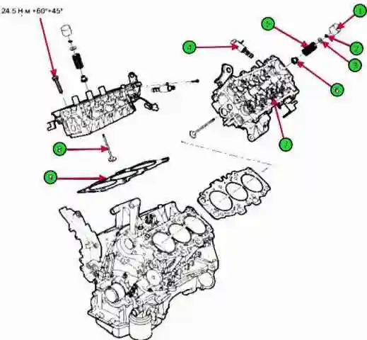
Tighten the cylinder head bolts with washer in the following order:
- - When assembling the washer, the marked surface must be at the top.
- - When installing the bolts, apply engine oil to the threads of the bolts and the surface of the washers. Tightening torque: 24.5 Nm

Using the special tool (09221-4А000), tighten the bolts using the angle tightening method.
Install the phase shifter assembly and timing chain sprocket with locating pin in the phase shifter mounted on the intake camshaft
Make sure the pin is not in the oil supply hole. Tightening torque: 66.7 - 78.5 Nm.
After installing the phase shifter bolts, turn the phase shifter assembly counterclockwise by hand, place the pin in the appropriate position.
Fix the hex area of the camshaft with a vise, then tighten the bolts. Do not fix the phase shifter or sprocket
Install the camshaft onto the cylinder head assembly.
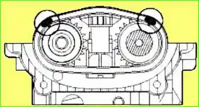
- Align the marks on the inlet and outlet sprocket of the camshaft chain and timing chain.
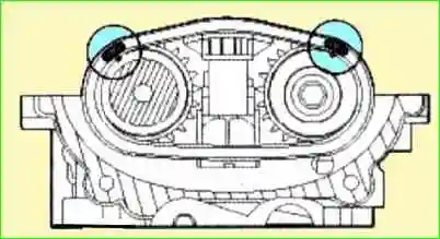
To assemble, both marks must be at the top
Install the intake and exhaust camshafts on the cylinder head, matching the marks.

Install the timing chain tensioner.
- - Install the pin by pressing the chain tensioner.
- - Install the tensioner (A) on the cylinder head.
- - Remove the pin from the tensioner after installation.

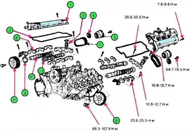
Install the camshaft bearing caps. Tightening torque: bolt (A: 6x38): 10.8 - 12.7 Nm, bolt (6: 8x38): 20.6 - 22.5 Nm.
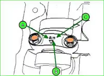
When installing the bearing caps, check for the marks as shown in the figure and install them in the correct position.
When installing the bearing caps, rotate the crankshaft to place the piston in the middle of the block as there may be a collision between the valve and the piston.

Using the special tool (09214-21000), install the camshaft oil seal.
Apply engine oil before installation
The camshaft cover must be firmly attached to the cylinder head assembly.
Do not create an off-center load.
Install the camshaft sprocket.
- - hold the hex area of the camshaft in a vise and screw in the bolts. Tightening torque: 88.3-107.9 Nm
- - In case of replacing the camshaft with a new one, check the valve clearance, then install the tappet.
To prevent check the collision of the valve and the piston, rotate the crankshaft sprocket 3 turns from TDC of the first cylinder, then measure the valve clearance.
Install the crankshaft position sensor connector bracket.

Install the rear cover (A) of the first row timing belt.

Install the rear cover (A) of the second row timing belt.
The length of bolt B is greater than the length of bolt C.
Install cylinder head cover
- Remove oil, dust and sealant from the cylinder surface before assembling the cylinder head cover.
Reassemble the cylinder head cover five minutes after applying sealant to the camshaft cover.
Tighten the cylinder head bolts in the correct order (A). Tightening torque: 7.8 - 9.8 Nm
- Do not start the engine within 30 minutes after installing the cylinder head cover.
Do not install an old cylinder head gasket.
Install the timing belt.
Align marks on left and right camshaft sprockets.
To prevent the valve and piston from colliding, rotate the crankshaft sprocket 3 turns from TDC of the first cylinder, then align the marks on the sprockets.
After aligning the marks on the camshaft sprockets, rotate the crankshaft sprocket 3 turns clockwise and align the crankshaft sprocket mark to set the No. 1 cylinder piston to TDC.
- Install the timing belt.
- Install thermostat assembly.
- Install the intake manifold assembly.
- Install the exhaust manifold assembly.
- Install the power steering pump.

Install the drive belt (A).

Install the heater hose.
Connect the brake vacuum hose (A).
Connect the engine wiring connectors.

Connect the first row camshaft position sensor connector (A).

Connect the connectors of the crankshaft position sensor (C), front and rear oxygen sensors (A, B) of the second row.

Connect the connectors of the water temperature sensor (B) and the camshaft position sensor (A) of the second row.

Connect the alternator (A) and A/C compressor (B) connectors.

Connect the connectors of the oil absolute pressure sensor (A), the throttle position sensor (B) and the positive crankcase ventilation valve (C)

Connect valve 1 and #2 connectors (A, B) and oil temperature sensor (C).

Connect the connectors of the injectors (A, B, C), ground wires (D), capacitor (E) and ignition coils (F).

Connect the front and rear oxygen sensor connectors (A) of the first row.

Connect knock sensor connectors #1 and #2 (A, B), injectors (C), ignition coil wiring (D) and VIS (E).

Install the fuel inlet hose (A) to the main pipe.

Install the upper (A) lower (B) radiator hose.

Install the air inlet hose and air filter assembly.
- Connect PCM connectors (D).
Install the air inlet hose and air filter assembly (C).
Connect the ventilation hose (B) to the filter hose.
Connect the mass air connector sensor connector.
Fill coolant.