The first maintenance of injectors is carried out after 250 hours of operation from the start of engine operation
The first check of the fuel injection pump and, if necessary, its adjustment is carried out after the end of the engine warranty period
In the future, service the injectors and check the fuel injection pump every 1000 hours of operation.
Injection pump maintenance
Injection pump tests must be carried out on filtered diesel fuel grade L in accordance with GOST 305 or a process fluid consisting of its mixture with industrial oil in accordance with GOST 20799, aviation oil in accordance with GOST 21743 or lighting kerosene in accordance with TU 38.401-58-10, having a viscosity of 5 to 6 mm 2/s (cSt) at a temperature of (20 ± 0.5) ºС.
It is allowed to use a mixture of working fluids consisting of 40% RZh-3 according to TU 38.101964 and 60% RZh-8 according to TU 025-041-00151911, or working fluid Volgol RZh-M according to TU 0253-044-34686523, having a viscosity from 5 to 6 mm 2/s (cSt) at a temperature of (20 ± 0.5) ºС.
The fuel temperature, measured at the outlet connection of the stand with the fuel line to the fuel injection pump being tested, when monitoring the magnitude and unevenness of cyclic flows, should be (32 ± 2) ºС.
Before starting the adjustment, rinse the oil cavity of the injection pump with clean diesel fuel and fill it with fresh engine oil to the level of the oil drain hole. During operation, plug this hole.
Before installing the injection pump on the stand, check that there is no axial play of the cam shaft.
If available, ensure a preload of 0.01 to 0.07 mm, having previously adjusted the axial clearance of the cam shaft from 0.03 to 0.09 mm by installing shims, controlled by a torque of 90 to 100 N (9 to 10 kgf) , then remove two gaskets 0.05 mm thick.
When the bearing cap bolts are tightened, the cam shaft should rotate freely in the bearings.
Checking and adjusting the injection pump should be done with a bench set of injectors having an effective flow area μf = 0.18 mm 2.
It is allowed to check and adjust the fuel injection pump with a working set of injectors. Each injector must be assigned to the corresponding section of the fuel injection pump, and installed in the engine cylinder that is connected to this section.
For a bench set of high-pressure fuel lines, steel pipes should be used in accordance with GOST 11017 with an internal diameter of (2 ± 0.05) mm, an external diameter of 7 mm and a length of (415 ± 3) mm.
Requirements for high pressure fuel lines - according to GOST 8519.
The difference in the capacity of the fuel lines that make up the bench set should not exceed ± 1 mm 3/cycle.
The throughput of the fuel lines is determined on one section of the injection pump with one injector and on one defoamer of the stand.
When adjusting the fuel injection pump with an ECS, it is necessary to use an adjustment stand and a hardware and software complex (SHC).
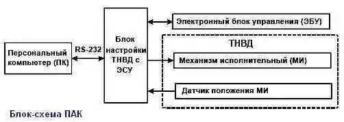
The block diagram of the PAC for running in, adjusting and checking the fuel injection pump with an ECS is shown in Figure 2.
Sequence of actions when working with the complex:
- − connect the PC, ECU, MI and MI position sensor to the fuel injection pump tuning unit with ESU;
- − turn on the power supply to the fuel injection pump tuning unit with the ESU;
- − turn on the power of the PC and load the operating system. PumpTune.exe should start automatically;
- − wait until the end of initialization, during which the PumpTune.exe program checks the connection with the ECU, MI and MI position sensor.
If there are errors, check the correct connection and electrical connections of the complex elements. If there are no errors, the main program window will load, containing a list of fuel injection pump models with ECS;
- − using the movement keys “↑” and “↓" on the PC keyboard, select the fuel injection pump model with ECS and confirm the selection by pressing the Enter key. The mode selection window will load;
- − similarly select the required mode from the “Running in”, “Adjustment”, “Check” or “Parameters” list.
The window corresponding to the selected mode will load with the information necessary for its implementation;
− the “Running in” mode allows you to control the position of the fuel injection pump rack between the positions of the switched off feed and the nominal feed.
To start the mode, you need to set the required camshaft rotation speed on the adjustment stand and press the Enter key in the “Running in” mode window.
To complete the “Running in” mode, you must press the Esc key and stop the rotation of the cam shaft on the adjustment stand;
− “Setting” and “Checking” modes allow you to set the injection pump rail to the required position. The lines in these modes represent control points of the corresponding modes.
Select contact The role point is made using the movement keys, after which you need to confirm the selection using the Enter key.
The injection pump rack will automatically move to the required position.
Next, on the adjustment stand, you need to set the required camshaft rotation speed and adjust the fuel supply.
At the control point corresponding to the engine idle mode, it is possible to adjust the rack position using the “+” and “-” keys on the PC keyboard in the range of ± 5% of the relative rack travel.
Exiting the “Setting” and “Running in” modes is carried out using the Esc key, after which it is necessary to stop the rotation of the cam shaft on the adjustment stand;
- − “Parameters” mode contains a list of necessary equipment for running in, configuring and checking the selected fuel injection pump model;
- − exit from the PumpTune.exe program by pressing the Esc key in the main window containing a list of fuel injection pump models with ECS, and confirming the exit by pressing the Enter key.
Next, you need to shut down the operating system, turn off the power to the PC and the fuel injection pump tuning unit with the ESU, disconnect the connectors of the ECU, MI and MI position sensor.
Before checking and adjusting the injection pump, it is necessary to check the tightness:
- low pressure and oil cavity systems, to do this, plug the bypass valve hole, the fuel injection pump outlet hole, the fuel injection pump fittings, the fuel take-off hole for the electric torch device, and install the rack cover.
Sealtly attach a tube with an internal volume of no more than 25 cm 3 to the oil drain screw (internal diameter no more than 8 mm), lower the free end of the tube into a container with fuel to a depth of no more than 20 mm.
Supply compressed air to the fuel supply screw of the injection pump and to the fuel supply hole of the TPN. The injection pump is considered suitable if, with a uniform increase in air pressure from 0 to 0.5 MPa (from 0 to 5 kgf/cm 2) for (10-20) s and holding for at least 20 s there is no release of air bubbles in the container with fuel;
- injection pump connections, to do this, supply compressed air to the oil drain screw and immerse the injection pump into a container with diesel fuel.
The injection pump is considered sealed if, at a pressure from 0.01 to 0.015 MPa (from 0.1 to 0.15 kgf/cm 2), no release of air bubbles is observed for at least 20 s through injection pump connections, except for the connection “rack lock screw – injection pump housing”.
When checking the injection pump, the following are controlled:
- the geometric start of injection (GNN) of fuel by fuel injection pump sections, determined by the moment the fuel flow stops from the injection pump fittings with the bypass valve hole plugged and the position of the rack corresponding to the nominal flow, i.e. the position at which the rack protrudes by an amount (* ?± 1) mm from the end of the fuel injection pump housing.(*?- value to be specified)
The fuel pressure at the inlet to the injection pump must be at least 0.15 MPa (1.5 kgf/cm 2).
The start of fuel injection by the first section of the injection pump must correspond to the rise of the pusher of this section from its lower position by an amount of (6.0 ± 0.05) mm.
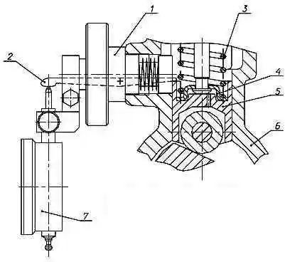
Measure the amount of lift of the pusher using the T9590-27 device, screwing it into a special threaded hole in the injection pump housing (Fig. 3).
At the moment the first section begins to pump fuel, the marks on the fuel injection start indicator and on the damper clutch must match.
Deviation from the coincidence of marks is allowed by no more than ± 15´.
The operating order of the sections (drive side) for the injection pump model 179: 1 – 3 – 6 – 2 – 4 – 5 – 7 – 8.
Camshaft rotation angles corresponding to fuel injection pump sections for injection pump model 179: 0º - 45º - 90º - 135º - 180º - 225º - 270º - 315º.
The deviation of the camshaft rotation angles corresponding to the fuel injection rate in the injection pump sections relative to the fuel injection rate of the first section is no more than ± 15´.
Adjustment of the amount of lift of the pusher is carried out by changing the height of two packages of adjusting shims under the section flange: when the height of the packages increases, the amount of lift of the pusher increases, and when it decreases, it decreases.
The number of pads in each bag and their heights should be the same on both sides, with the thickest pad on top.
To do this you need:
− check the pressure at which the injection valves begin to open, which should be from 0.02 to 0.1 MPa (from 0.2 to 1.0 kgf/cm 2).
Control the pressure of the start of opening of the discharge valves by the moment the start has expired release of fuel from fuel lines with an internal diameter of (2 ± 0.05) mm or fuel injection pump fittings with a gradual increase in fuel pressure at the injection pump inlet, the position of the rack corresponding to the fuel supply being turned off, and the bypass valve hole being plugged;
− check the fuel pressure in the line at the inlet to the injection pump, which should be (0.175 ± 0.025 MPa) [(1.75 ± 0.25) kgf/cm 2] at the rated speed camshaft (950 ± 5) min -1 and fully depressed control pedal.
If necessary, unscrew the bypass valve plug and adjust the opening pressure with washers;
− check the presence of the rack's travel reserve for turning off the fuel supply relative to its travel, limited by the stop of the electromagnet MI, which should be within (1.5 ± 0.1) mm.
If necessary, make adjustments by turning the MI, loosening the tightening of the nuts securing the MI cover;
- − check the rotation speed of the injection pump camshaft, corresponding to the beginning of turning off the starting feed, regardless of the position of the control pedal, which should be within (230...250) min -1;
- − check, with the control pedal fully pressed, the rotation speed of the injection pump camshaft corresponding to the start of the MI action, which should be from 990 to 1010 min -1;
− check, with the control pedal fully pressed, the rotation speed of the injection pump camshaft, corresponding to the complete shutdown of the fuel supply by the injection pump sections, which should be (60-120) min -1 greater than the rotation speed of the start of the action of the MI;
− check, and, if necessary, adjust with a set of injectors, the average cyclic fuel supply and unevenness of fuel supply across sections, which must correspond to those indicated in the table.

Notes:
The average cyclic fuel supply is defined as the arithmetic average of the actual values of the cyclic fuel supply of all sections of the injection pump.
The unevenness of fuel supply across sections is calculated using the formula:

- - qцmax – maximum cyclic fuel supply by sections, mm 3/cycle;
- - qцmin – minimum cyclic fuel supply by sections, mm 3/cycle.
When the control signal from the stand changes, corresponding to a change in air pressure within the specified limits, the change in the average cyclic fuel supply should not exceed ± 2 mm 3/cycle.
Injector maintenance
During maintenance, adjust the injection start pressure at each nozzle to 29.4+1.2 MPa (300+12 kgf/cm 2).
It is recommended to make adjustments on a special stand that meets the requirements of GOST 10579 (type KI 3333). Methods for adjusting nozzles are indicated in the “Nozzle” section.
Check that the sprayer is tight against the needle locking cone and that there are no leaks at the high pressure fuel line seals.
To do this, create a fuel pressure in the nozzle at (1-1.5) MPa [(10...15) kgf/cm 2] below the injection start pressure. In this case, there should be no leakage of fuel from the spray holes within 15 s.
It is allowed to moisten the nozzle of the sprayer without the fuel coming off in the form of a drop.
Check the tightness of the high-pressure fuel line seals by holding it under pressure for 2 minutes. During this time, no loose drops of fuel should form at the upper end of the nozzle nut (when installing the nozzle at an angle of 15º to the horizontal).
Check the mobility of the needle by pumping fuel through a nozzle adjusted to a given injection start pressure on a pressure testing stand at an injection frequency of 30 to 40 per minute.
It is allowed to check the mobility of the needle simultaneously with checking the quality of fuel atomization.
Check the quality of fuel atomization on a pressure testing stand by pumping fuel through a nozzle adjusted to a given injection start pressure at an injection frequency of 60 to 80 per minute.
The quality of fuel atomization is considered satisfactory if the atomized fuel emerging from the injector nozzle is misty, without continuous streams and easily visible local concentrations.
The beginning and end of the injection must be clear. Injecting fuel with a new injector is accompanied by a characteristic sharp sound. After injection is completed, the nozzle of the sprayer can be moistened without forming a drop.
The absence of a sharp sound from used injectors when checking them on a manual stand is not a sign of poor-quality operation of the injectors.
Germetic Check the integrity of the seals, connections and outer surfaces of the low-pressure cavity of the injectors by pressure testing with air under pressure (0.5 ± 0.1) MPa [(5 ± 1) kgf/cm 2].
Passing air for 10 s is not allowed. Check the tightness of the connection “nozzle - nozzle nut” for 10 s by pressure testing with air under pressure (0.5 ± 0.1) MPa [(5 ± 1) kgf/cm 2] when air is supplied from the side spray nozzle on a special stand.
Passing air through the thread of the nozzle nut when immersing the nozzle in diesel fuel is not allowed.
If fuel leaks along the cone or the needle is stuck, replace the atomizer assembly.
The atomizer body and needle form a precision pair in which replacement of one of the parts is not allowed.
If one or more spray holes of the nozzle become coked or clogged, disassemble the nozzle, clean its parts and rinse thoroughly in clean gasoline or diesel fuel.
Sequence of disassembling injector 51-21:
- − unscrew the sprayer nut;
- − remove the atomizer, protecting the needle from falling out.
Clean the outside of the sprayer using a wooden block soaked in engine oil, a wire brush or sandpaper with a grain size no coarser than M 40.
Rinse the internal cavities of the sprayer body in gasoline, clean the spray holes, if necessary, with steel wire with a diameter of 0.18 to 0.21 mm.
It is not allowed to use sharp hard objects or sandpaper to clean the internal cavities of the sprayer body and needle surfaces.
Before assembly, thoroughly rinse the sprayer body and needle in filtered diesel fuel.
After this, the needle, extended from the sprayer body by one third of the length of the guide surface, when tilting the sprayer at an angle of 45º, should smoothly, without delay, completely lower into the sprayer body under the influence of its own weight.
Assemble the injector in the reverse order of disassembly. When tightening the nozzle nut, turn the nozzle against the direction of screwing the nut until the locking pins stop and, holding it in this position, screw the nut by hand, then tighten it completely.
Tightening torque of the injector nozzle nut 51-21 – 49.03 to 60.80 Nm (from 5.0 to 6.2 kgf m);
After assembling the injector, adjust the injection start pressure and check the quality of fuel atomization.
List of equipment for monitoring fuel injection pump with ESU
A stand with a drive power of at least 11 kW, with equipment and devices that meet the requirements of GOST 10578.
Hardware-software complex (SHC) for running-in, regulation and testing of fuel injection pumps with ECS, consisting of hardware:
- − fuel injection pump adjustment unit,
- − personal computer (PC)*,
- − cable for connecting to a computer (RS-232),
- − cable for connecting the actuator and position sensor; and the software installed on the PC hard drive:
- PumpTune.exe program;
- file of running-in modes, adjustment and testing of fuel injection pump Pump Tune.xml.
Note: *recommended PC configuration:
- - 800 MHz processor, no less
- - RAM 32 MB, no less
- - CD-ROM drive,
- - COM port (RS-232),
- - operating system MS Windows 95 and higher.
Middle-class accuracy scales according to GOST 29329.