Inspect the cylinder block. If it has cracks, it needs to be replaced
In order to check the tightness of the cooling jacket of the block, it is necessary to plug all the holes in the block with wooden plugs, except for one, to which the compressed air hose is connected.
Immerse the block in a bath of water and apply compressed air at a pressure of 1.5 atm.
Air bubbles will come out in places where the cooling jacket leaks. If a leak is found, replace the unit.
In the same way, check the oil channels of the block.
Inspect the cylinders.
If there are scratches, scuffs, shells, etc. on the cylinder mirror, bore the cylinders to the repair size and honing.
There are two overhaul cylinder sizes shown in the table.
Pistons and piston rings of the same repair dimensions are supplied as spare parts.
All cylinders must be bored to the repair size, even if defects are found in only one.
Check clearances between cylinders and pistons. The nominal gap should be within 0.024–0.048 mm, the maximum allowable gap is 0.25 mm.
To ensure the clearance, the cylinders and pistons are divided by diameter into five size groups A, B, C, D and D (see table).
The letter identifying the cylinder group is inked on the left outer side of the block, opposite each cylinder.
The clearance can be determined by measuring the diameter of the piston and cylinder.
The piston diameter is measured in a plane perpendicular to the piston pin axis, 8.0 mm below the piston pin axis.
The cylinder diameter is measured in at least three belts within 15–100 mm from the upper plane of the block, in two perpendicular directions.
Check the clearances between the main bearing shells and the crankshaft journals.
The gap should be between 0.019-0.073 mm.
Clearances can be calculated by measuring the diameters of the crankshaft journals and journal holes with the main bearing shells and caps installed, or by measuring them with a calibrated plastic wire.
Measure the gaps in the following order:
- - Clean the crankshaft journals and bearing shells.
- - Lay the crankshaft on the bed of the main bearings with the liners installed.
- - Put on the crankshaft journals trimmed calibrated plastic wire.
- - Install the main bearing caps with the liners installed in them, tighten the cap bolts and tighten to 100 Nm (10 kgf m). In this case, it is forbidden to turn the crankshaft.
- - Remove the main bearing caps and determine the gap by the flattening of the wire according to the scale printed on the wire package.
Before assembling the engine, it is advisable to go over the articles again: Maintenance and repair of the ZMZ-405, ZMZ-406 engine
And then go back to this article and assemble the engine in accordance with the paragraphs. The main thing in this matter is not to rush, and do everything carefully.
For assembly, you need to purchase all the necessary tools. Some tools can be borrowed as they are only needed for engine overhauls.
All fasteners must be tightened in accordance with the torque table.
Let's consider the assembly of the engine in detail:
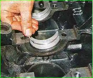
We install the engine block on the stand in an upside down position.
We put liners with a groove and an oil supply hole in the bed of the main bearings.
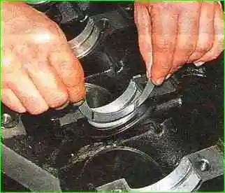
On both sides of the central bed, we install two thrust half rings without protrusions, turning them with transverse grooves to the cheeks of the crankshaft.
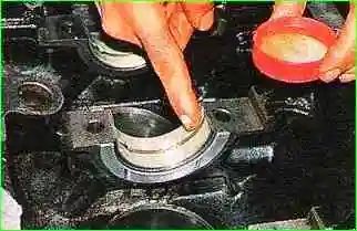
Lubricate the liners and main journals of the crankshaft with clean engine oil.
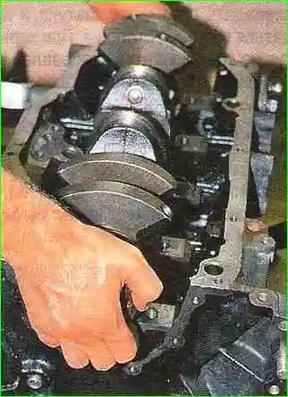
We put the crankshaft in the cylinder block.
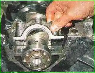
After inserting the liners into the main bearing caps, lubricate them with clean engine oil and install the caps on the crankshaft journals in accordance with you numbers from 1 to 5 beaten on them, starting from the front of the block.
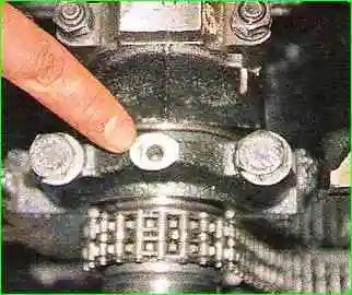
The third cover is not marked
In its grooves we insert two persistent half rings with ledges.
We lubricate, bait the bolts and, evenly wrapping them, press the covers into the seats.
The right and left stops of the lid have different lengths, so the upside down lid will not fit into the seat.
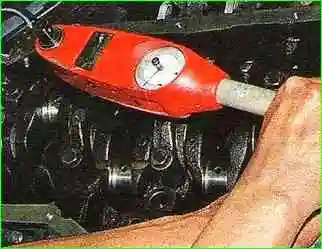
We tighten the bolts of the main bearing caps.
Turn the crankshaft by hand.
Rotation should be free and uniform without jamming with little effort.
The axial play of the crankshaft must not exceed 0.36 mm.
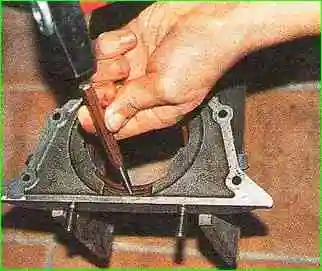
Change the cuff in the back cover of the block.
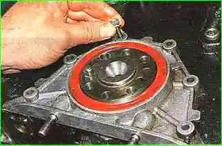
Reinstall the cover with a new gasket.
Installing the flywheel (see “Replacing the ZMZ-406 crankshaft oil seals”).
We assemble the connecting rod and piston group (see How to assemble the connecting rod and piston group ZMZ-406).
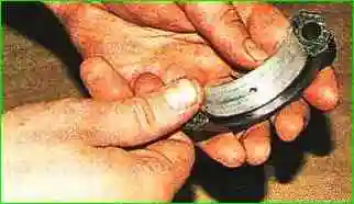
We insert new liners into the connecting rod and its cover.
Lubricate them, as well as piston rings, cylinder walls and connecting rod journals with clean engine oil.
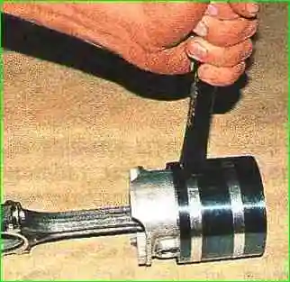
We put a fixture on the piston and crimp the rings, “helping” them to shrink with light blows on the crimp with a wooden hammer handle.
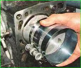
Turn the piston with the inscription “FRONT” on the boss to the front of the block and insert it into the cylinder, the number of which is stamped on the lower head of the connecting rod and duplicated on its cover
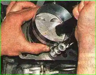
Tapping through the wooden spacer on the bottom of the piston, we sink it into the cylinder until it stops, control the movement of the connecting rod to the crankshaft journal.
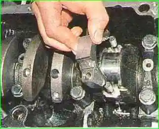
Install the connecting rod cap.
The number stamped on the cap must match the connecting rod number and be on the same side.
In this case, the ledge on the connecting rod cap is directed towards the front of the engine.
In the same way, we install the remaining pistons in the block.
Tightening the nuts of the connecting rod caps
We turn the crankshaft by the flywheel, the movement should be without jamming, but the force will increase.
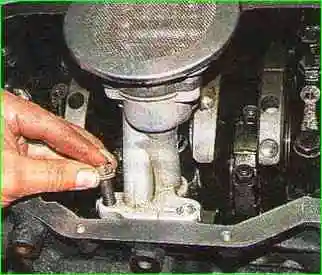
Install the oil pump with a new gasket
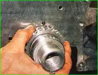
Lubricate the bushing, install the oil pump drive (see “Oil pump drive ZMZ-406”).
We set the mark of the crankshaft sprocket opposite the alignment mark.
Installing the damper of the lower chain (see “Replacing ZMZ-406 chains”).
We assemble the oil pump drive by lubricating the drive gears, intermediate shaft bushings and the shaft itself with engine oil.
Putting the chain on the crankshaft sprocket, install the intermediate shaft sprocket on the axle in a position where the alignment marks match (the chain on the side of the damper must be tensioned).
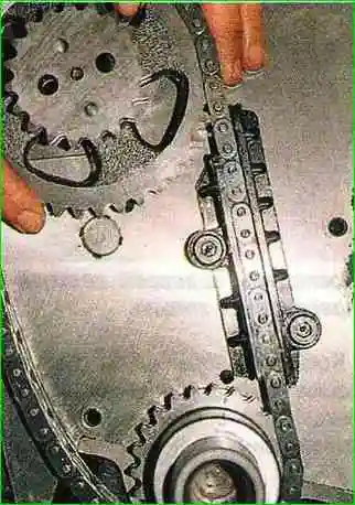
Tighten the sprocket bolts and bend the edges of the locking plate; install the upper shoe of the chain tensioner; we put the lubricated chain on the small sprocket of the intermediate shaft.
We change the cuff in the front cover of the block (see “Replacing the ZMZ-406 crankshaft oil seals”) and install the cover with a new gasket and the generator bracket.
Tighten and tie the upper timing chain to the generator bracket.
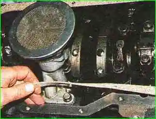
We lay a new gasket and install the oil pan.
We put a pulley on the crankshaft shank and tighten the ratchet bolt, install the tension roller with the bracket, install the lower chain hydraulic tensioner
We install the clutch crankcase booster, block head, accessories and attachments (see the relevant articles).
Table - Size groups of cylinders and pistons
Group - cylinder diameter, mm - piston diameter mm:
- A - nominal size 92.036 - 92.024 - nominal size 92.000 - 91.988;
- A - 1st oversize * 92.536 - 92.524 - 1st oversize 92.500 - 92.488;
- A - 2nd oversize ** 93.036 - 93.024 - 2nd oversize 93.000 - 92.988;
- B - nominal size 92.048 - 92.036 - nominal size 92.012 - 92.000;
- B - 1st repair size 92.548 - 92.536 - 1st repair size 92.512 - 92.500;
- B - 2nd repair size 93.048 - 93.036 - 2nd repair size 93.012 - 92.000;
- B - NS 92.060 - 92.048 - NS 92.024 - 92.012;
- B - 1st TS 92.560 - 92.548 - 1st TS 92.524 - 92.512;
- B - 2nd TS 93.060 - 93.048 - 2nd TS 93.024 - 92.012;
- B - NS 92.072 - 92.060 - NS 92.036 - 92.024;
- D - 1st TS 92.572 - 92.560 - 1st TS 92.536 - 92.524;
- G - 2nd TS 93.072 - 93.060 - 2nd TS 93.036 - 92.024;
- D - nominal size 92.084 - 92.072 - nominal size 92.048 - 92.036;
- L - 1st TS 92.584 - 92.572 - 1st TS 92.548 - 92.536;
- L - 2nd TS 93.084 - 93.072 - 2nd TS 93.048 - 92.036
* 1st repair size increased by 0.5 mm
** 2nd repair size increased by 1.0 mm


