The PAZ-32053-07, PAZ-4234, and their modifications belong to Category M3, Class II, and Classes I-II, according to Appendix No. 7 of the "Consolidated Resolution on Vehicle Design" (SR.3). These buses are designed for passenger transportation on roads classified as operating categories I, II, and III, excluding roads with mountainous terrain. These buses are manufactured in version U1 according to GOST 15150 and are designed for operation at ambient temperatures from -45°C to +40°C and relative humidity up to 75% at 15°C. A distinctive feature of these Class I buses is their smaller tires (245/70R 19.5). The PAZ-32053-07 and PAZ-4234 bus families have the following modifications, listed in the table.
Bus model designation - VIN code:
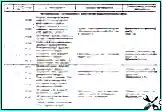
PAZ-32053-07 - single-door (base model, D-245.7E2 engine) - X1M3205CR
PAZ-32053-110-07 single-door (base model, D-245.9E2 engine) - X1M3205C2
PAZ-32054-07 two-door (D-245.7E2 engine) - X1M3205HR
PAZ-32054-110-07 two-door (D-245.9E2 engine) - X1M3205H2
PAZ-32053-27 - cargo-passenger (D-245.7E2 engine) - X1M3205CD
PAZ-32053-110-27 cargo-passenger (engine D-245.9E2) - X1M3205C3
PAZ-32053-57 with increased comfort, single-door (D-245.7E2 engine) - X1M3205CK
PAZ-32053-110-57 with increased comfort, single-door (D-245.9E2 engine) - X1M3205C4
PAZ-32053-67 - with increased thermal insulation, single-door (D-245.7E2 engine) - X1M3205CM
PAZ-32053-110-67 with increased thermal insulation, single-door (D-245.9E2 engine) - X1M3205C5
PAZ-32054-67 - with increased thermal insulation, two-door (D-245.7E2 engine) - X1M3205HM
PAZ-32054-110-67 with enhanced thermal insulation, two-door (D-245.9E2 engine) – X1M3205H5
PAZ-32053-87 - for funeral services (D-245.7E2 engine) - X1M3205CH
PAZ-32053-110-87 for funeral services (D-245.9E2 engine) - X1M3205CH
PAZ-4234 two-door (base model, D-245.9E2 engine) - X1M4234K0
PAZ-423402 - two-door, enhanced comfort (D-245.9E2 engine) - X1M4234K2
PAZ-423403 - single-door, enhanced comfort ( D-245.9E2) - X1M4234K3
The PAZ-32053-27 and PAZ-32053-87 models are not public transport vehicles (route vehicles).
")

")
")
")
")
")
")
")