The transfer case of the VAZ-2121 car is used to distribute torque between the drive axles of the car
The Niva is equipped with a two-stage transfer case, with a forced-locking center differential and manual control.
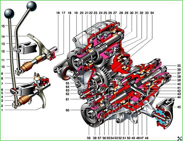
Transfer case with drive: 1 - differential lock clutch fork; 2 - differential lock fork rod; 3 - rod protective cover; 4 - lock washer; 5 - lever axis bushing; 6 - lever axis; 7 - fork locking bolt; 8 - differential lock indicator lamp switch; 9 - gear shift fork rod; 10 - differential lock lever; 11 - spacer sleeve; 12 - gear shift lever axis; 13 - brackets; 14 - gear shift clutch fork; 15 - gear shift lever; 16 - detent spring bushing; 17 - detent spring and ball; 18 - input shaft flange; 19 - front cover; 20 - input shaft oil seal; 21 - bearing thrust ring; 22 - input shaft front bearing; 23 - high gear pinion; 24 - gear shift clutch; 25 - transfer case housing; 26 - low gear pinion; 27 - input shaft rear bearing; 28 - mounting ring of the rear bearing of the drive shaft; 29 - drive shaft; 30 - sleeve; 31 - hub; 32 - rear cover; 33 - rear bearing of the intermediate shaft; 34 - intermediate shaft; 35 - rear axle drive shaft bearing; 36 - differential rear bearing; 37 - flange; 38 - rear axle drive shaft oil seal; 39 - differential rear housing; 40 - pinion thrust washer; 41 - rear axle drive pinion; 42 - satellite axle; 43 - retaining ring; 44 - spring washer; 45 - suspension bracket; 46 - satellite thrust washer; 47 - front axle drive housing; 48 - satellite; 49 - differential driven pinion; 50 - Front differential housing; 51 - Retaining ring; 52 - Spring washer; 53 - Front differential housing bearing; 54 - Differential lock clutch; 55 - Front differential bearing mounting ring; 56 - Oil deflector; 57 - Front axle drive shaft oil seal; 58 - Front axle drive shaft bearing; 59 - Front axle drive shaft flange; 60 - Front axle drive shaft; 61 - Oil drain plug; 62 - Speedometer drive driven gear; 63 - Intermediate shaft roller bearing; 64 - Filler plug; 65 – speedometer drive pinion
The gearbox has two speeds (low and high) with gear ratios of 1.2 and 2.135, which allows increasing the transmission ratios and doubling the total number of gears, which increases the vehicle’s cross-country ability.
The center differential provides constant drive to the front and rear drive axles.
There is also a forced differential lock, which increases the vehicle’s cross-country ability.
The differential lock and gear shifting are performed using levers mounted on the transfer case.
The transfer case housing 25, cast from aluminum alloy, houses the drive and intermediate shafts, the drive shafts of the front and rear axles, and the differential housing on bearings.
Freely mounted on the drive shaft are helical gears of the highest 23 and lowest 26 gears, having toothed rims and being in constant engagement with the gears of the intermediate shaft, which is made in the form of a gear block.
Between gears 23 and 25 on the shaft, the hub of the gear shift clutch 24 is fixedly fixed, having external splines on which a sliding clutch is mounted.
When the highest gear is engaged, the gear shift clutch 24 locks the freely rotating gear 23 on the drive shaft 29, and when the lowest gear is engaged, it locks the gear 26.
The gear block of the intermediate shaft 34 is in constant engagement with the helical driven gear 49, attached with bolts to the differential housing, which consists of two parts.
On the differential housing, on the splines, there is a movable locking clutch 54 differential.
Inside the differential housing, there is an axle with two satellites that are engaged with gears that are connected to the splined ends of the drive shafts of the front and rear drive axles of the vehicle.
The front axle drive shaft is longer than the rear axle shaft and has a toothed ring for locking the differential.
When the differential is locked, the movable clutch 54 connects the shaft to the differential housing.
The gear shift mechanism of the transfer case includes: shift lever 15, slider, fork, and ball lock.
The lever is pivotally mounted on the axle in the bracket eyes.
The lever has a shaped end that enters the groove of the slider and is sealed in it by a spring.
A fork is fixed on the slider, which enters groove of the clutch 24 for gear shifting.
The ball lock holds the slider in the neutral and engaged positions.
The differential lock drive has a device similar to the gear shift mechanism.
The drive consists of a lever 10, a slider with a fork and a ball lock.
The transfer case is attached to the car body on two supports 45 mounted on the axles.
Each support consists of a bracket in which a rubber cushion is pressed.
Adjusting linings are installed under the transfer case supports for centering and correct installation in relation to the gearbox.
Possible malfunctions, their causes and methods of elimination
- Cause of malfunction
Method of elimination
Floor vibration in the area front seats when starting the vehicle and accelerating:
- Transfer case and/or gearbox mounts are loose
Tighten the unit mounts, check the centering of the transfer case relative to the gearbox
- Transfer case mounts, gearbox mount are damaged
Replace the mounts, center the transfer case relative to the gearbox
- Transfer case relative to the gearbox is not centered
Center the transfer case relative to the gearbox
- Elastic coupling bolts and/or flanges are deformed
Replace the deformed parts (if necessary, the intermediate shaft assembly)
- Elastic coupling fastening bolts to its flange on the secondary shaft of the gearbox and/or intermediate shaft flange nuts to the transfer case input shaft flange
Tighten the fasteners, check the alignment of the transfer case relative to the gearbox
Floor vibration in the front seat area when the vehicle is moving at a speed of 80–100 km/h in direct gear:
- Increased imbalance of the intermediate shaft: the relative position of the parts during assembly is disturbed, the elastic coupling is delaminating, incorrect assembly or wear of the constant velocity joint, the balancing washers under the elastic coupling bolts are lost
Replace the intermediate shaft assembly
- The bolts and/or flanges of the elastic coupling are deformed
Replace the deformed parts (if necessary, the intermediate shaft assembly)
- The bolts securing the elastic coupling to its flange on the secondary shaft of the gearbox and/or intermediate shaft flange nuts to the transfer case input shaft flange
Tighten the fasteners, check the alignment of the transfer case relative to the gearbox
- Seizure of the constant velocity joint: no grease in the joint, its parts are deformed, improper assembly
Disassemble the joint, clean the parts, replace the grease. If the parts are heavily worn or deformed, replace the intermediate shaft assembly
- Seizure of the cardan joints of the front or rear shafts
Lubricate the joints. If lubrication does not eliminate the jamming, replace the joint or shaft assembly
- Increased imbalance of the cardan shafts
Replace the shafts as an assembly
- Increased imbalance of the center differential due to a manufacturing defect or a violation of the mutual arrangement of parts during assembly
Replace the differential
Noise when turning or slipping wheels:
- Worn or chipped teeth of the satellites or axle drive gears
Replace worn or broken parts
- Tight rotation of the satellites on the axle
Clean burrs on the axle and in the holes of the satellites with a file, replace worn and deformed parts
- Wear of the spherical (inner) surface of differential housing
Replace differential housing or differential assembly
- Seizure of axle drive gears in differential housing
Replace worn and deformed parts. By selecting thrust washers, set the axial clearance of the gears to 0–0.10 mm, monitoring the torque of resistance to rotation
- Large axial clearance of the axle drive gears in the differential housing
By selecting thrust washers, set the axial clearance of the gears to 0–0.10 mm, monitoring the torque of resistance to rotation
Gears or differential lock are difficult to engage:
- The sliding clutch moves with difficulty on the splines of the hub or differential housing
Clean the splines from dirt, file off burrs with a needle file, replace parts with crushed splines
- Nicks on the teeth of spur (small) gears of the highest and lowest gears, on the teeth of the couplings and splines of the front axle drive shaft
Clean the parts, file off burrs with a file, replace parts with crushed splines or worn teeth
- Fork or rod is deformed
Straighten or replace parts
- Drive levers are deformed
Straighten levers
- Drive levers are jammed on axles
Disassemble the connection, clean the parts from dirt, if necessary, replace the lever axle, its bushings
- Oil in the transfer case is too thick
Use oil in accordance with the clmatic conditions
Spontaneous disengagement of gears or differential lock:
- Damage or wear of gear teeth and couplings, nicks on splines
Replace worn couplings or gears. Remove nicks with a file
- Drive parts are deformed
Straighten or replace parts
- Lock springs have lost their elasticity, dirt in the lock holes, lock wear
Clean parts, replace worn ones
Oil leak from the transfer case:
- Oil seal wear
Replace oil seals
- Heavy wear, nicks on the surfaces of shafts and rods on which the oil seals operate
Sand small damage with fine-grained sandpaper and polish.
When installing a new oil seal, you can slightly under-press it, preventing distortion (if necessary, place spacers up to 1 mm thick under it) so that the edge of the oil seal operates on the unworn part shaft.
If there is significant damage, replace the shafts and seals
- The transfer case housing covers have become loose, their gaskets are damaged
Tighten the threaded connections. Replace the gaskets (you can use a sealant)
- The plugs are not tightly screwed in
Tighten the plugs (you can put them on a sealant)
- The cap nut of the speedometer drive on the transfer case is not tightened
Tighten the nut
There are traces of grease on the intermediate shaft joint boot:
- The protective boot of the joint is damaged, its clamps are loose
Inspect the joint, if there is play, replace it.
If there is no play, and there is a little dirt in the grease, without disassembling the joint, remove as much grease as possible with a screwdriver and put in new grease (CV joint-4). Replace the damaged boot, tighten (replace) the clamps
")

")
")
")
")
")
")
")