Prepare the car for work. Disconnect the negative terminal of the battery
Removal
Remove the instrument panel.
Drain the coolant.
For cars equipped with an air conditioning system, the refrigerant should be discharged from the air conditioning system in accordance with the operating instructions for the service equipment.
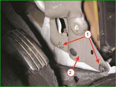
Lower mount of the instrument panel cross member reinforcement: 1 - instrument panel cross member reinforcement mounting bolt: 2 - panel cross member reinforcement instruments
Using a 13 mm socket head, unscrew the two bolts 1, Figure 1, of the lower fastening of the reinforcement 2 of the instrument panel cross member to the body base.
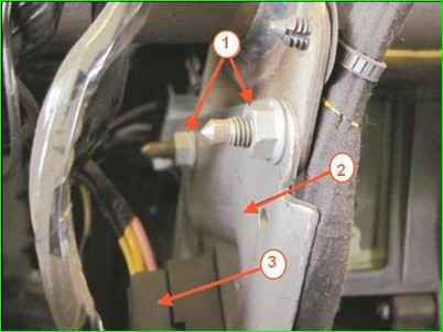
Upper fastening of the instrument panel cross member reinforcement: 1 - instrument panel cross member reinforcement fastening nut; 2 - instrument panel cross member reinforcement; 3 - wiring harness block
Using a 13 mm head, unscrew the two nuts 1, Fig. 2, of the upper mount of the amplifier 2 of the instrument panel cross member. Disconnect the wiring harness block 3 and remove the amplifier 2.
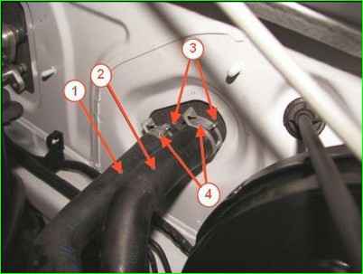
Fastening the heating system hoses: 1 - heater outlet hose: 2 - heater inlet hose; 3 - heater radiator pipes; 4 – clamp
Using a clamp puller, squeeze and move the two clamps 4, Figure 3.
Remove the heater inlet 2 and outlet 1 hoses from the heater radiator pipes 3.
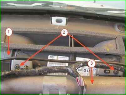
Fastening the air distribution unit to the instrument panel crossbar: 1 – air distribution unit; 2 - screw for fastening the unit to the crossmember: 3 - instrument panel crossmember
Using a T20 Torx head, unscrew the two screws 2, Figure 4, fastening the air distribution unit 1 to the crossmember 3.
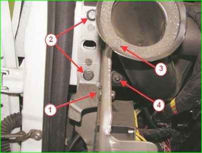
Fastening the instrument panel crossmember and the left front air duct: 1 - instrument panel crossmember; 2 - crossmember fastening screw; 3 - front air duct: 4 - air duct mounting screw
Using a T20 Torx head, unscrew screw 4, Figure 5, securing the left front air duct and remove the air duct, similarly remove the right air duct.
Using a 13 head, unscrew two screws 2 securing crossbar 1 on the right and left of the instrument panel, move the crossbar aside.
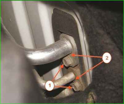
Fastening the evaporator pipes: 1 - pipe fitting mounting bolt; 2 - air conditioning system pipelines
For vehicles equipped with an air conditioning system: from the engine compartment, using a 10 mm head, unscrew the two bolts 1, Figure 6, securing the pipelines to the evaporator, disconnect the connections and install technological plugs on the pipelines and the evaporator unit.
Disconnect the wiring harness blocks from the fan, additional resistor.
Remove the heater unit assembled with the heating, air conditioning and ventilation control unit.
Installation
Installation is carried out in the reverse order of removal, while:
- for vehicles equipped with an air conditioning system: remove the plugs from the pipelines and the evaporator unit, install new sealing rings on the pipelines.
Apply oil to the sealing rings compressor;
- perform vacuuming of the air conditioning system and load the system with refrigerant, according to the operating instructions for the service equipment.
Check the operability of the heating, air conditioning and ventilation system.
Disassembling the heater
Remove the heating, air conditioning and ventilation control unit by disconnecting the damper drive rods from the heater unit.
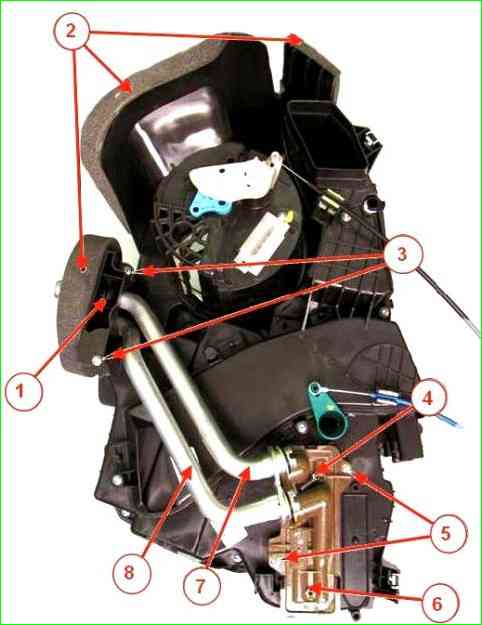
Unit heater: 1 - bracket for pipes: 2 - foam seals; 3 - screw for fastening the bracket for pipes: 4 - screw for fastening the pipes: 5 screw for fastening the radiator; 6 - radiator; 7 - inlet pipe: 8 - outlet pipe
Remove the foam seals 2, Figure 7.
Using a T20 Torx head, unscrew the two screws 3 and remove the bracket for pipes 1.
Using a T20 Torx head, unscrew the screw 4 and remove the inlet pipes 7 and outlet pipes 8 of the heater radiator 6.
Using a T20 Torx head, unscrew the two screws 5, press the three clamps, remove the radiator 6 from the heater body and drain the remaining coolant (replaceable T20 Torx head, ratchet).
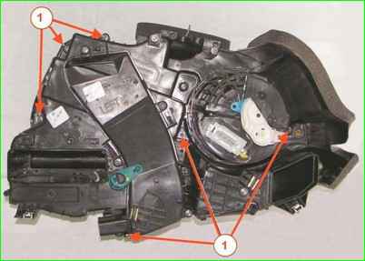
Unscrew the six screws 1, Figure 8, and separate the heater unit into two parts.
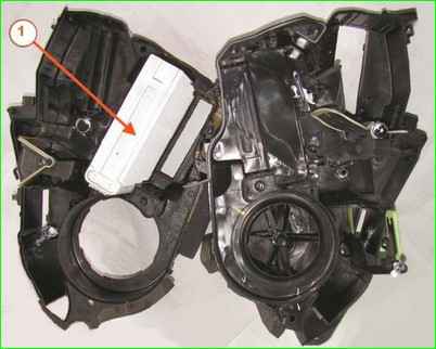
Remove evaporator 1, Figure 9, from the unit heater.
Assembly
Assemble the heater unit in the reverse order, while:
- - install new foam seals;
- - install new sealing rings on the heating system pipes.
Removing and installing ventilation and heating system elements
Removing the heater radiator
Drain the coolant in accordance with the requirements of TI 3100.25100.06005.
Remove the visor, instrument cluster and central floor tunnel trim.
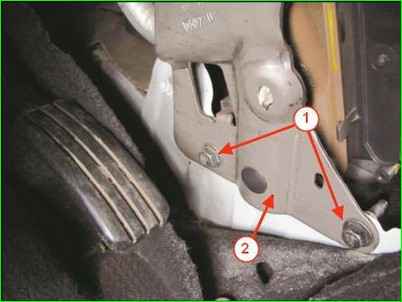
Lower mount of instrument panel cross member reinforcement: 1 - instrument panel cross member reinforcement fastening bolt: 2 - instrument panel cross member reinforcement
Using a 13 mm socket, unscrew the two bolts 1, Fig. 10, fastening the reinforcement 2 of the instrument panel cross member to the body base.
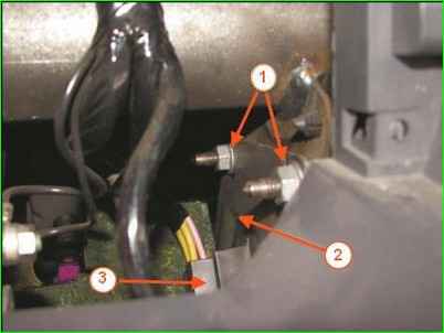
Upper mount of instrument panel cross member reinforcement: 1 - instrument panel cross member reinforcement fastening nut; 2 - instrument panel cross member reinforcement; 3 - wiring harness block
Using a 13 mm head, unscrew the two nuts 1, Fig. 11, of the upper mount of the cross member reinforcement 2 through the window in the instrument panel, disconnect the wiring harness block 3 and remove the reinforcement 2.
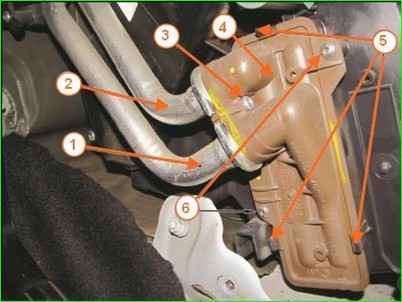
Heating system radiator: 1 - heating system radiator outlet pipe; 2 - heating system radiator inlet pipe; 3 - screw for fastening the inlet and outlet pipes: 4 - heating system radiator; 5 - retainer: 6 - heating system radiator mounting screw
Using a T20 Torx head, unscrew screw 3, Figure 12, and disconnect the inlet 2 and outlet 1 pipes from the heater radiator 4.
Using a T20 Torx head, unscrew two screws 6, press three retainers 5 and remove radiator 4 from the heater housing
Installation
Installing the heating radiator is carried out in the reverse order of removal, while:
- install new sealing rings on the heating system pipes.
Removing the additional resistor of the heater fan
The additional resistor of the heater fan is located on the heater housing on the side of the pedal block.
Remove the instrument panel (information on removal instrument panel).
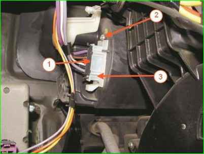
Additional heater fan resistor: 1 - wiring harness block; 2 - additional heater fan resistor mounting screw; 3 - additional heater fan resistor
Disconnect connector 1, figure 13, of the wiring harness, unscrew screw 2 securing resistor 3, remove the resistor from the heater unit (replaceable Torx T20 head, ratchet).
Installation
Install the removed parts in the reverse order of removal.
Removing the heater fan
Set the air distribution switch handle in the passenger compartment to this position. panel ь devices 
Disconnect the wiring harness block 1, Figure 14.
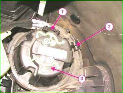
Heating system fan: 1 - wiring harness block; 2 - fan retainer; 3 - heating system fan
Press the lock 2, turn fan 3 clockwise by a quarter of a turn and remove it from the heater housing.
Installation
Install the heater fan in the reverse order of removal.
Removing the heating, air conditioning and ventilation control unit
Remove the central instrument panel trim.
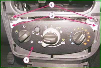
Fastening the control unit heating, air conditioning and ventilation: 1 - screw for fastening the heating, air conditioning and ventilation control unit; 2 - clamps; 3 - heating, air conditioning and ventilation control unit
Unscrew the two screws 1, Fig. 15, securing the control unit 3 to the instrument panel, squeeze the clips 2 and remove the unit (replaceable Torx T20 head, ratchet).
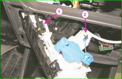
Heater unit flap control rods: 1 - air recirculation flap rod; 2 - heater radiator flap rod; 3 - air distribution flap unit rod; 4 - Instrument cluster wiring harness connector
Disconnect connector 4, Figure 16, of the instrument cluster wiring harness.
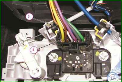
Heater unit flap control rods: 3 - air distribution flap unit rod; 4 - instrument panel wiring harness block
Disconnect the damper drive rods from the control unit
Install the heating, air conditioning and ventilation control unit in the reverse order
Replacing the cabin filter
The cabin air filter is located in the heater unit under the instrument panel on the glove compartment side.
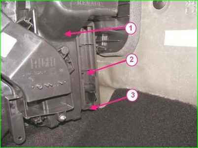
Cabin filter: 1 - heater housing; 2 - cabin filter; 3 - glove compartment cabin filter retainer.
Press retainer 3, figure 18, remove cabin filter 2, located in heater housing 1 from the side
Install a new cabin filter element.
Please note that most vehicle variants do not have a cabin filter! You can modify it and install a filter


