We replace the clutch when the driven and driving discs are worn
Install the car on an inspection ditch or lift
Remove the gearbox.

Unscrew the ten mounting bolts and remove the clutch housing.

Secure the flywheel with a screwdriver 1, unscrew evenly diagonally the six bolts 2 securing the pressure plate to the flywheel and remove the pressure plate 3 and the driven disks, while holding the driven disk.

Unscrew the four bolts securing the clutch housing amplifier to the engine block, lift the rear part of the engine and remove clutch housing amplifier 1
Inspection and testing of clutch parts
Clean the pressure and driven disks, as well as the working surface of the flywheel, from dust and dirt.

Inspect the driven disk. Cracks on the parts of the driven disk are not allowed.
Check the wear of friction linings 1.
If the heads of the rivets 2 are recessed less than 0.2 mm, the surface of the friction linings is oily or the rivet joints are loose, then the driven disk (or friction linings) must be replaced.
Check the secure fixation of damper springs 3 in the sockets of the driven disk hub.
If the springs are broken, the disc must be replaced.
On the friction washer 4, located under the pressure spring 5 of the torsional vibration damper, no signs of wear, overheating or mechanical damage are allowed.
Check the runout of the driven disk if warping is detected during a visual inspection. If the runout value exceeds 0.7 mm, replace the disc.
Inspect the working friction surfaces of the flywheel and pressure plate, paying attention to the absence of deep marks, scuffs, nicks, obvious signs of wear and overheating.
Loosening the rivet connections of the pressure plate parts is not allowed.
If the indicated defects are present, it is recommended to replace the components.

By external inspection, evaluate the condition of the support rings 1 and the diaphragm spring 2 of the pressure plate.
Backup rings must not have cracks or signs of wear.
Cracks in the diaphragm spring are not allowed.
The contact points (shown by the arrow) of the spring petals with the clutch release bearing must be in the same plane and have no obvious signs of wear.

Checking the location of the ends of the spring petals and their adjustment is carried out using a special device or on a removed flywheel.
To check, it is necessary to mount the pressure disk 2 on the removed flywheel 3, having previously placed three washers 1 8 mm thick under the working surface of the pressure disk, placing them relative to each other at approximately an angle of 120°.
Measure the distance from the end of the flywheel to the end of petal 4. This size should be (42.5±2) mm.
Check this size on other petals in the same way.
It is allowed to protrude (sink) the spring petals relative to each other by no more than 0.25 mm.
Otherwise, the ends of the petals that do not lie in the plane must be bent.
After checking the position of the petals, check the amount of movement of the working part of the pressure disk.
To check, it is necessary to apply force to all petals 4 so that they move from their original position to a depth of 8.5 mm, while the gap between pressure plate 2 and washers 1 should be at least 1.3 mm.
Remove the washers; to do this, increase the force on the ends of the petals so that they move approximately 10 mm.
Installing the clutch

Lubricate the front bearing of the input shaft located in the flywheel with Litol-24 grease.
Check that the clutch driven disc can easily move axially along the splines of the input shaft. If movement is difficult, remove burrs from the splines.
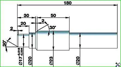
Insert a mandrel made in accordance with the specified dimensions into the front input shaft bearing located in the flywheel.

Install the clutch driven disc onto the mandrel.
At the same time, orient the driven disk so that the protruding part of the driven disk hub faces the pressure plate.

Install the pressure plate and tighten the six bolts securing it without tightening.
If a centering mandrel is not available, a spare input shaft can be used.
In this case, place the pressure and driven disks on the input shaft in accordance with their orientation.
Insert the input shaft into the front bearing located in the flywheel and tighten the six pressure plate mounting bolts without tightening.

Finally tighten the six pressure plate mounting bolts evenly diagonally with a torque of 20–25 Nm (2–2.5 kgcm).
Check the tightness of the ball pin mounting nut on the clutch housing.
Lubricate the ball surface of the pin with a thin layer of Litol-24 lubricant.

Install the clutch housing booster, if it was removed, and tighten the four bolts securing the booster to the cylinder block to a torque of 29–36 Nm (2.9–3.6 kgcm).
Install the crankcase onto the cylinder block and tighten its mounting bolts.