In a steering mechanism with a built-in hydraulic booster, instead of a roller, a three-tooth sector is cut on the bipod shaft, and the role of a worm is played by a screw connected to a piston-rack mounted on two thrust bearings, the preload of which is adjusted by a nut
In the steering gear housing there is a hydraulic booster cylinder, in which a piston-rack moves along a screw.
The piston is integral with the ball nut and has teeth that engage with the teeth of the bipod shaft sector.
The piston divides the cylinder into two cavities. When the steering wheel is stationary, the pressure in them is the same.
Depending on the direction of rotation of the steering wheel, the corresponding cylinder cavity is connected through a hydraulic distributor to the high-pressure injection line, and the other to the outlet line.
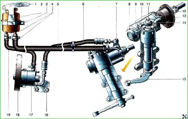
The fluid (oil) pressure in the power steering hydraulic system is created by a vane-type pump with a belt drive from the crankshaft pulley, mounted on the front of the engine.
The expansion tank of the power steering hydraulic system contains a filter element that traps particles larger than 45 microns.
The steering drive consists of steering link rods, bipod rods and levers.
Self-tensioning dismountable hinges with hemispherical pins are pressed into the eye of the pendulum lever and into the ends of the rods.
The steering linkage rods have adjusting tubes, and corrugated rubber seals with a metal clip are pressed onto the shoulders of their tips.
The joints of the bipod linkage and the pendulum arm are protected by rubber cap seals.
")

")
")
")
")
")
")
")