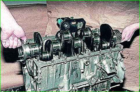
Defection and repair of the GAZ-3110 cylinder block
Inspect the block, if there are cracks, replace it

Check the tightness of the cooling jacket of the block; to do this, plug all the holes in the block with wooden plugs, except one, to which connect a hose for supplying compressed air
Lower the block into a bath of water and apply compressed air under a pressure of 1.5 atm.
Air bubbles will escape in areas of leakage. In the same way, check the tightness of the oil passages of the block.
If a leak is detected, the unit must be replaced.
Inspect the cylinder liners.
If there are scratches, burrs, holes, etc. on the cylinder bore, bore the liners to the repair size or replace them.
Two repair sizes of sleeves are provided. Spare parts are supplied with pistons and piston rings with the same repair dimensions.
All liners must be bored to the repair size, even if defects are found in only one.
Check the clearances between the pistons and liners.
The nominal gap should be in the range of 0.024–0.048 mm, the maximum permissible is 0.25 mm.
To ensure the size of the gap, the pistons and liners are divided by diameter into five size groups A, B, C, D and D.
The letter indicating the group of the sleeve is printed on the lower centering part of the sleeve.
The clearance can be determined by measuring the diameter of the piston and liner.
The piston diameter is measured in a plane perpendicular to the piston pin axis and 8.0 mm below the pin axis.
The diameter of the sleeve is measured in at least three zones within 15–100 mm from the upper edge of the sleeve, in two perpendicular directions.
When replacing liners, new liners are inserted into the cylinder block so that the letter indicating the liner group is located in the transverse plane.
The sleeve must fit into the block completely freely.
The sleeve installed with a copper gasket in the block should protrude above the surface of the block by 0.02–0.1 mm.
The difference in the protrusion of the liners across the cylinders should be no more than 0.055 mm (this is ensured by selecting the liners according to their length or by settling them with deformation of the copper gasket).
Before removing the sleeves from the block, they must be marked so that during reassembly they can be installed in the same place in the same position as they were before disassembly.
When using old liners, you need to remove the unworn belt in the upper part of the liner, flush with the cylinder mirror.
Check the gaps between the main bearing shells and the crankshaft journals; they should be in the range of 0.02–0.073 mm.


