Cars are equipped with a five-speed gearbox. Weight (without refueling) - 32 kg
The presence of a 5th overdrive gear provides, in real operating conditions, fuel savings of 07-1.0 liters per 100 km compared to a four-speed gearbox, a maximum speed of 115 km/h, reduces engine speed at high vehicle speeds, increasing its durability.

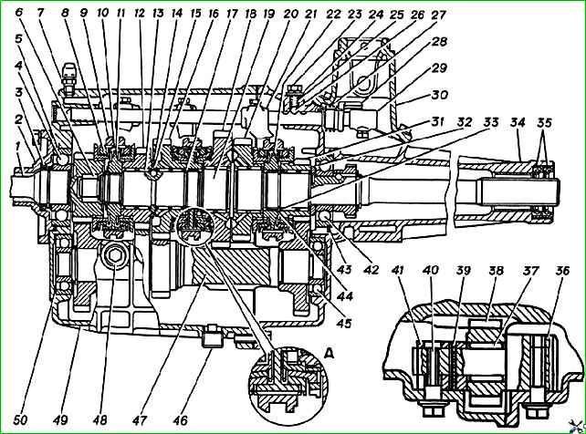
Gearbox (longitudinal section): A - two-cone synchronizer; 1 - input shaft; 2 - input shaft bearing cover; 3 - oil seal; 4- ball bearing of the input shaft; 5 - retaining ring; 6 - roller bearing of the secondary shaft; 7 - breather; 8 - blocking ring; 9 - engagement clutch; 10- synchronizer block; 11 - clutch hub for 3rd, 4th gears; 12 - 3rd gear gear; 13 - needle bearing of the gear; 14 - retaining ring of half rings; 15 - half ring; 1 6- second gear; 17- retaining ring; 18 - 1st gear gear; 19 - secondary shaft; 20 - reverse gear; 21 - 5th gear and reverse fork; 22 - hub of the 5th gear and reverse clutch; 23 - bolt securing the retainer plate; 24 - plate; 25 - clamp spring; 26 - ball of clamps; 27- locking sleeve spring; 28 - locking sleeve; 29 - head of the 5th gear and reverse gear rod; 30 - shift lever housing; 31 - 5th gear gear; 32 - thrust washer; 33- spacer sleeve; 34 - rear gearbox housing; 35 - oil seal; 36 - axis of the reverse intermediate gear; 37- needle bearing of the reverse intermediate gear; 38 - reverse intermediate gear; 39 - pin; 40 - bolt securing the bushing of the reverse intermediate gear axis; 41 - bushing for the reverse intermediate gear axis; 42 - ball bearing of the secondary shaft; 43 - retaining ring of the secondary shaft bearing; 44 - retaining ring; 45 - bearing; 46 - oil drain plug; 47 - gear block; 48 - oil filler plug; 49 - front gearbox housing; 50 - shims
The gearbox housing is made of aluminum alloy and consists of two parts - front 49 and rear 34 housings with mounting sleeves pressed into the front housing and connected to each other with ten bolts.
The input shaft gear, as well as the 1st, 2nd, 3rd, 5th gears and reverse gears mounted on the secondary shaft 19, are in constant mesh with the gears of the gear block 47, have helical teeth and rotate on needle bearings with plastic cages.
The reverse intermediate gear rotates on bulk rollers with a diameter of 3 mm on an axis, the supports of which are located in both crankcases.
All gears are equipped with inertia-type synchronizers, the toothed rims of which are connected to the gears via small splines.
Synchronizers for 3rd, 4th, 5th gears and reverse have gears made integral with cones.
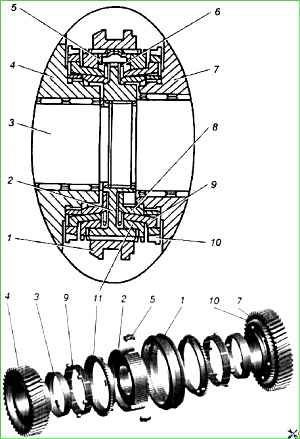
The equalization of the revolutions of the engaged gear to the revolutions of the secondary shaft, necessary for shockless gear shifting, is achieved using the braking torque arising due to friction forces on the outer surface of the gear ring gear cone and the inner conical surface of the outer (blocking) ring 8 of the synchronizer, connected through hubs 11 and 22 with a secondary shaft 19.
The crankcases are centered to ensure the necessary alignment of the shaft supports and the holes for the switching mechanism rods

The 1st - 2nd gear synchronizer is double-cone, has an increased braking torque due to the additional friction surface formed by the outer conical surface of the inner ring 8 connected to the hub and the inner conical surface on the middle ring 9 of the synchronizer, connected by three protrusions (protrusions fit into the holes on the ring gear 10) with the engaged gear.
It should be noted that until 06/01/03, a single-cone synchronizer was installed in the gearbox, unified with synchronizers for 3rd, 4th, 5th gears and reverse.
The gears are engaged by connecting the internal teeth of the couplings 9 with the external gear rims of the synchronizers.
The sides of the teeth of the couplings and synchronizer rims are beveled in the inside at an angle of 4° and when in the on position form a lock that prevents the gears from turning off automatically.
Protrusions on the teeth of the synchronizer rims limit the movement of the clutches when engaging gears.
Axial forces from the oblique teeth of the secondary shaft gears are perceived by retaining rings 17 and 44, thrust washer 32, the shoulder of the secondary shaft and two thrust half rings located in the groove on the secondary shaft, which are covered by ring 14
Ball bearings of the primary and secondary shafts are mounted on the shafts using spring and retaining rings and are fixed in the crankcases using external retaining rings.
The gear block rotates on ball or tapered bearings installed in blind sockets of the front and rear crankcases.

Preload is carried out by placing adjusting shims 50 into the front crankcase socket when assembling.
The rims of the constant mesh gears of the 2nd, 3rd and 5th gears of the gear block are mounted with an interference fit on the intermediate shaft, on which long teeth are cut, which simultaneously serve as the rims of the 1st gear and reverse gears of the gear block.
The head of the axis 36 of the reverse intermediate gear is installed in the bed of the rear gearbox housing and is secured in it with a locking bolt.
The opposite end of the axle enters the bushing 41 and is fixed in it with a split elastic pin; the bushing is attached to the bed in the front crankcase also with a locking bolt.
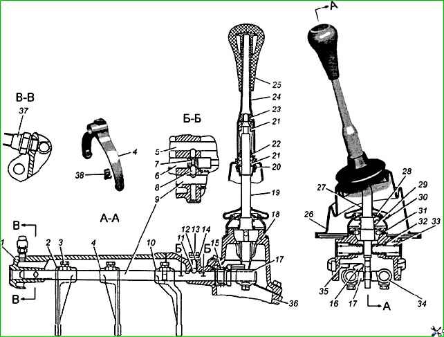
The shift mechanism contains rods on which gear shift forks and heads 29 are mounted, in the grooves of which the lower end of the shift lever is located.
The rods are fixed in the on and off position using balls 11 (Fig. 3) and springs 15.
A locking device, consisting of two locking plungers and a locking pin, protects the gearbox from engaging two gears at the same time.
In addition, between the head of the reverse rod and the wall of the rear housing there is a locking sleeve 16 with a spring 15, which makes it impossible to accidentally move the shift lever from the 5th gear engaged position to the reverse position.
The gear shift lever is equipped with a damper device that eliminates its rattling during resonance at high engine speeds, and is located in a special housing 18, attached to the rear crankcase from above.
With the help of springs and fuses, the lower head of the shift lever in the neutral position is always located in the head of the 3rd and 4th gear shift rod.
Oil drain plug 46 has a magnet that catches small metal particles contained in the oil - wear products of gearbox parts.
Five-speed gearboxes for Volga passenger cars and GA3el cars are unified in most parts.
The gearbox of GA3el cars differs in the input shaft (the number of teeth is 25 instead of 26), the pinion ring of the gear block drive (36 teeth instead of 35) and the speedometer drive gear, a higher shift lever housing and the lower part of the gear shift lever.


