Defect elimination: The crankshaft is turned by the starter, but the engine does not start
First of all, you need to check and eliminate faults not related to the CMSUD:
- - check the condition of the air filter and clean it if necessary;
- - check the correct installation of the camshaft drive (valve timing) and, if necessary, install;
- - check the compression pressure in the engine cylinders (compression) and, if necessary, repair the engine malfunction;
- - check the tightness of the connections of the intake pipe and air ducts with the engine and, if necessary, restore the tightness of the connections.
Next, you need to check the operation of the KMSUD in the mode of displaying fault codes, see the article “Checking the operation of the KMSUD in the mode of displaying fault codes of the GAZ-3110”, and eliminate the identified malfunctions.
Check for sparking
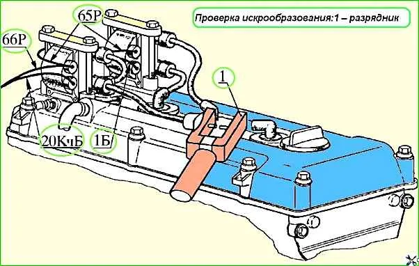
Check for the presence of high voltage using a high-voltage spark gap with a spark gap of 4 - 5 mm, connected between the high-voltage wire from the ignition coil and the ground (Fig. 1).
When the engine is cranked by the starter, sparking should be observed in the spark gap.
If there is no sparking, disconnect the wiring harness block from the control unit.
Forcibly turn on the main relay by closing contacts 3 and 19 and, turning on the ignition, check for the presence of 12V voltage at terminals 27, 37, 18, 20 and 1 of the block.
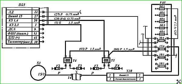
If there is no voltage, check the low voltage circuit of the ignition coils (Fig. 2) for a break or broken contacts at the wire connection points.
If no faults are found in the circuit, replace the ignition coil or control unit.
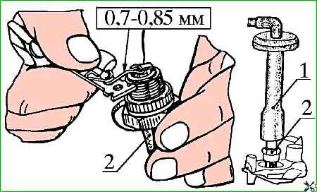
Check the condition of spark plugs 2 (Fig. 3) by unscrewing them one by one from the cylinder head.
Candles should not be damp, should not have cracked insulators, damage to the electrodes and large deposits on the electrodes.
The gap between the electrodes of the spark plugs should be in the range from 0.7 to 0.85 mm.
If necessary, dry the spark plugs, clean the electrodes from carbon deposits, set the specified gap between the spark plug electrodes, or replace the spark plugs with new ones.
Screw the spark plugs 2 with new sealing rings into the cylinder head and put the tips 1 of the high voltage wires from the ignition coils on them in the established order shown in Fig. 1.
Check the serviceability of the fuel supply system
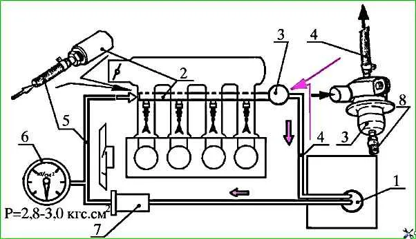
Connect pressure gauge 6 to fuel supply line 5 (Fig. 4) using a high pressure hose.
- - Before performing the operation, remove the 15A fuse to prevent accidental starting of the electric fuel pump.
- - When disconnecting fuel hoses, cover the connection point with a rag, avoiding spilling and splashing of fuel, follow fire safety rules.
- - Install the previously removed 15A fuse and turn on the ignition. In this case, the electric fuel pump should turn on, run for 5 - 7 seconds and then turn off.
- - Check the tightness of pressure regulator 3.
To do this, remove the vacuum supply hose 4 from the pressure regulator fitting 3, loosening the clamp securing it. If there is a gasoline leak from the fitting, replace the regulator.
- Record the pressure value using the pressure gauge leniya in the system.
The pressure in the fuel line must be maintained at 2.6 - 3.0 kg/cm 2 and not decrease over time.
A lower or higher pressure indicates a system malfunction.
If the pressure is less than the specified value, check:
- - throughput of pipelines and hoses, absence of contamination, bending, etc.;
- - condition of fuel filters.
- - serviceability of the pressure regulator. Replace the faulty regulator;
- - serviceability of the fuel pump. Replace faulty fuel pump.
If the pressure is more than 3 kg/cm 2 check:
- - throughput of pipelines and return drain hoses, absence of contamination, bending, etc.;
- - serviceability of the pressure regulator. Replace the faulty regulator;
- Check the system for tightness.
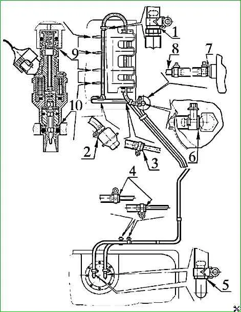
Gasoline leaks at the junctions of pipelines and hoses 1 - 8 (Fig. 5), as well as at the junctions 9 and 10 of the injectors with the fuel distributor and the intake pipe are not allowed.
If a gasoline leak is detected, find the cause and eliminate the leak.
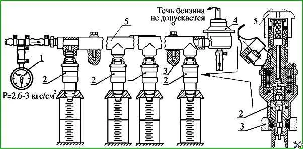
- If necessary, remove the fuel distributor 5 with injectors 2 and pressure regulator 4 from the engine and check the identity of the flow characteristics of injectors 2 and the tightness of the pressure regulator 4 on a special stand 3 at a gasoline pressure of 3.0 kg/cm 2 and temperature from 15˚ to 20˚С.
Replace the pressure regulator if the following is detected during the tests:
- - gasoline leakage from the regulator vacuum supply fitting;
- - the fuel pressure supplied to the fuel distributor 5 is not maintained within the specified limits.
Replace the injectors with new ones if the following injector malfunctions are detected:
- - needle sticking in the open position;
- - presence of gasoline leakage when the injector is closed;
- - underestimated or overestimated performance in relation to other nozzles;
- - when a voltage of 12 V is applied, the nozzle does not fire (you cannot hear a click from raising the spray needle).
- - Install the fuel line to the engine.
If there is no special stand for checking injectors, check the tightness of the injector using compressed air.
To check, apply compressed air to the nozzle at a pressure of 2.8 - 3 kg/cm, and lower the spray nozzle into kerosene