To reduce the force applied to the brake pedal, a two-chamber vacuum booster is installed between it and the main brake cylinder, triggered by vacuum in the engine intake pipe
The amplifier consists of a housing 11, a housing cover 6, a thrust cover, into which pistons 5 and 10 with diaphragms 7 and 8 are installed.
On the threaded end of the piston connector 22, a secondary piston 5 is attached using a nut, and a piston 10 and a diaphragm 18 are attached to the flange part of the connector using six bolts, which are screwed into the valve body 15.
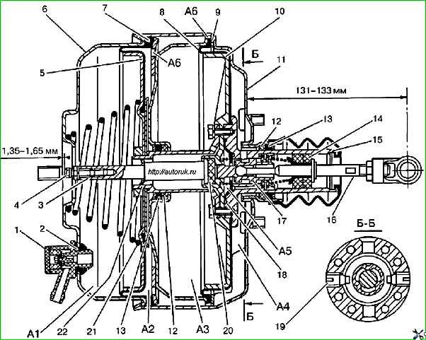
In the valve body 15, two screws 19 secure a pusher 16 with a piston 17 and a filter 14.
A reaction washer 20 is installed in the piston 10, through which the total force from the pusher 16, directly connected to the brake pedal, and from both pistons of the amplifier is transmitted to the pusher 3.
To ensure the release of the system, a gap is required between the pusher 3 and the primary piston of the main brake cylinder.
The clearance is ensured using adjusting bolt 4.
The head of the bolt should be recessed 1.35-1.65 mm relative to the mating plane of the cover to which the master cylinder flange is attached.
Operation of the vacuum amplifier
The vacuum created during engine operation is transmitted through a rubber hose and check valve 1 to cavity A1.
Since cavity A1, through the central hole in connector 22 and holes in the connector flange and piston 10, is constantly connected to cavities AZ and A5, a vacuum is also created in these cavities.
When the brake pedal is not pressed, cavity A5, through the gap between the valve diaphragm 18, piston 17 and the radial holes of connector 22, communicates with cavity A4, which, in turn, is connected to cavity A2 through holes A6 in the thrust cover.
Consequently, a vacuum is created in all cavities A1, A2, AZ, A4 and A5 of the amplifier.
Check valve 1 maintains the greatest vacuum in the amplifier, which is formed during engine operation.
When you press the brake pedal, the piston 17, under the action of the pusher 16 connected to the pedal, touches the valve diaphragm 18 and interrupts the communication of the cavities A1, AZ, A5 with the cavities A4 and A2.
Then the piston 17, moving the diaphragm 18, lifts it from the seat on the valve body 15,
As a result, atmospheric air, passing through filter 14, holes in housing 15, enters diaphragm 18 and then through radial drillings in valve body 15 - into cavity A4 and through holes A6 into cavity A2, that is, to pistons 5 and 10 .
Atmospheric air enters cavities A4 and A2 until the diaphragm 18 of the valves, under the influence of the jet washer 20, sits simultaneously on the seats of the piston 17 and housing 15, blocking the flow of air.
Thus, the tracking action of the system is carried out through the reaction washer, i.e. the force created by the amplifier is directly proportional to the force applied by the driver to the brake pedal.
As the force on the pedal increases, the piston 17 compresses the jet washer 20, moves the diaphragm 18 away from the seat in the valve body 15, and an additional amount of atmospheric air again enters the pistons 5 and 10, which increases the effect of the amplifier.
The force from the driver’s foot and from the pistons 5 and 10 of the amplifier is transmitted through the reaction washer to the pusher 3 and then to the pistons of the master cylinder.
When the pedal is released, the piston 17 moves away from the diaphragm 18, allowing it to move onto the seat in the housing 15.
In this case, the access of atmospheric air is stopped, and the vacuum is transmitted through the resulting end gap between the piston 17 and the diaphragm 18 from cavity A5 to cavities A4, A2.
The cavities A1, A2, AZ, A4 and A5 will again communicate with each other, and the pistons, under the action of spring 21, will return to their original position and the braking will stop. The amplifier is ready for new braking.
If the engine stops, the vacuum maintained in the booster by the check valve allows for 2-3 effective braking of the vehicle.
If there is no vacuum in the booster, pusher 3 will only be affected by the force applied by the driver to the brake pedal.
Removing the vacuum booster

Loosen the fastening clamp 1 and disconnect the hose 3 from the check valve 2 of the vacuum booster.
Remove the brake master cylinder

Remove the cotter pin 1, unscrew the fastening nut 2, remove the axle 5 and disconnect the booster pusher 4 from the brake booster lever 3, while removing the plastic bushings 6.

Unscrew the four fastening nuts 1 and remove the vacuum booster 3 from the bracket 2.
Checking the vacuum booster
When the force on the brake pedal increases, it is necessary to check the functionality of the vacuum booster.
Press the brake pedal all the way several times with the engine not running and, holding the pedal pressed, start the engine.
In this case, due to the pressure difference in the cavities of the amplifier, the brake pedal should move forward.
If this does not happen, check the vacuum booster hose connections for tightness and, if necessary, eliminate air leaks.
If this does not give a positive result, then the amplifier is faulty and must be replaced.
To check the tightness of the vacuum booster, you need to open the hood and start the engine for 1 minute.
Approximately 30 seconds after the engine has been turned off, press the brake pedal 2 times, and you should hear a characteristic hiss of air entering the amplifier. Otherwise, replace the amplifier.
Blow out the hose with the check valve at both ends. Air should only flow from the check valve side. Otherwise, replace the check valve.
Installing a vacuum booster

Install the vacuum booster in the reverse order of removal.
Before installation, check the gap between the end of the vacuum booster cover and the adjusting bolt 1.
The gap should be 1.35-1.65 mm.
If the gap value differs from the specified value, unscrew the lock nut 2 and, by rotating the adjusting bolt 1, set the required gap. After this, tighten locknut 2.
")

")
")
")
")
")
")
")