Replacing the clutch cable
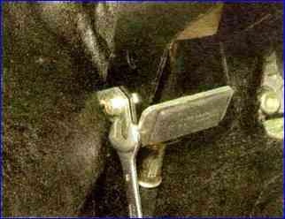
In the cabin, under the instrument panel, use a 8mm wrench to unscrew the nut securing the cable sheath bracket to the pedal assembly bracket.
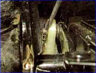
Use a slotted screwdriver to pry up the spring clip and remove it from the groove of the clutch pedal pin.
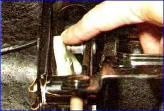
Remove the eye of the housing of the automatic cable length adjustment mechanism from the clutch pedal pin.
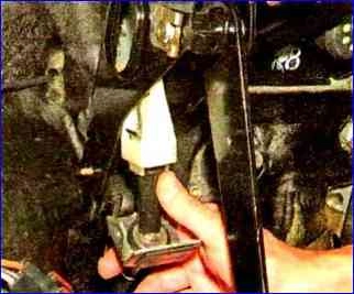
We remove the upper part of the cable from the pedal assembly bracket.
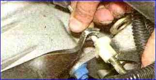
In the engine compartment, pulling the cable forward, remove the cable lead from the groove of the clutch release fork lever
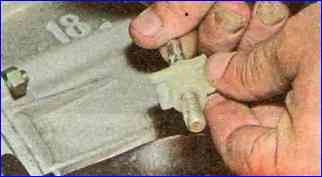
Rotating counterclockwise, unscrew the leash from the threaded end of the cable.
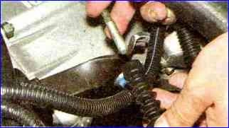
Remove the rubber protective cover from the cable end
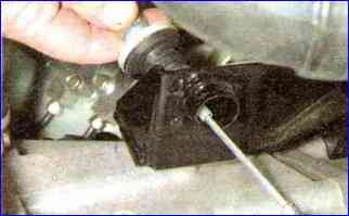
Remove the end of the cable sheath from the hole in the bracket on the gearbox
In the passenger compartment, remove the cable sealing cover from the hole in the front panel and pull the cable into the passenger compartment
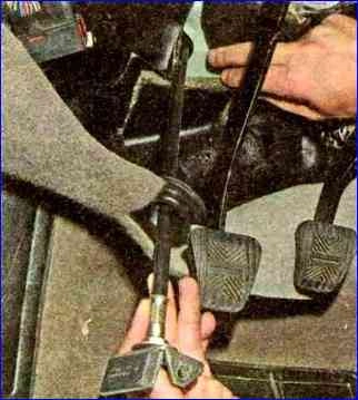
Before installing the cable, check the condition of the plastic bushing on the pedal pin (Fig. 10).
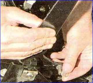
Replace the worn bushing with a new one and apply grease to the pin.
Install the cable in the following sequence:
- - we pass the cable through the hole in the front panel from the passenger compartment into the engine compartment;
- - install the sealing cover in the hole in the front panel;
- - put the automatic cable length adjustment mechanism on the pedal pin and fasten it;
- - screw a plastic leash onto the threaded end of the cable so that the end of the cable tip is flush with the end of the leash;
- - insert the leash into the groove of the clutch release fork lever;
- - adjust the clutch drive.
To do this, pull the cable forward by the threaded end until it stops, overcoming the force of the clutch pedal spring, and hold the cable in this position.
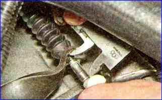
Using a caliper we measure the distance from the end of the plastic guide to the clutch release fork lever, which should be 27 mm (Fig. 11).
If necessary, rotate the leash to achieve the required distance.
When removing the load (releasing the cable), the leash should be adjacent to the fork lever without play.
After this, press the clutch pedal three times to activate the automatic length adjustment mechanism dew.
Full pedal travel should not exceed 146 mm.
Replacing the clutch housing and driven disc
We carry out the work on an inspection ditch or overpass.
Remove the gearbox.
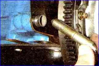
Screw the M12x1.25 pin (or the bolt securing the clutch housing to the cylinder block) into the threaded hole of the cylinder block.
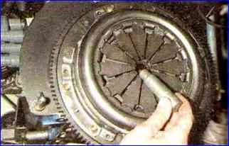
Insert a mandrel or primary shaft from the VAZ classic gearbox into the holes of the crankshaft and driven disk.
We insert a mandrel so that the basket and driven disk do not fall while unscrewing.
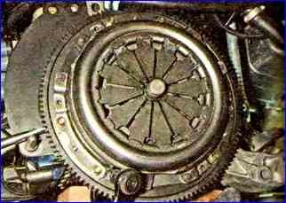
Having installed the mounting blade between the teeth of the flywheel and resting it on the screwed-in pin or bolt, use a 8-mm head to unscrew the six bolts securing the clutch housing to the flywheel.
We unscrew the bolts evenly, each no more than one turn per pass, so as not to deform the clutch casing.
If it is difficult to unscrew the bolts, tap their heads with a hammer with a soft metal tip.
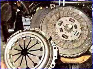
Remove the clutch basket
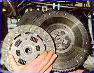
Remove the clutch driven disc
Install the clutch basket and driven disk in reverse order
During installation, we orient the clutch driven disc with the protruding part of the hub towards the basket.
Insert the centering mandrel into the splines of the driven disk and insert the shank of the mandrel into the hole in the crankshaft flange.
Tighten the basket fastening bolts evenly diagonally.
Final tightening torque 19-30 Nm.
After installing the gearbox, we adjust the clutch cable.
Removing the clutch release mechanism
Removing the gearbox
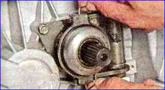
We move the ends of the spring bracket away from the legs of the clutch release bearing housing.
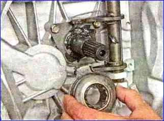
Remove the clutch release bearing assembly with the casing from the guide sleeve.
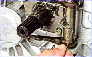
Remove the spring clip of the clutch release bearing.
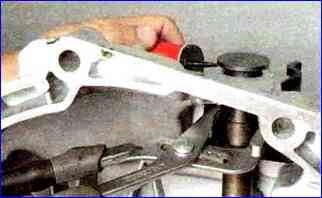
To remove the clutch release fork, use sliding pliers to squeeze the petals of the plastic bushing and use a slotted screwdriver to pry up the bushing.
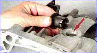
Remove the bushing from the hole in the clutch housing.
During subsequent assembly, the protrusion on the bushing shoulder should fit into the groove (shown by the arrow) in the crankcase.
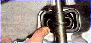
From inside the clutch housing, squeeze out the dirt-proof rubber cover of the clutch release fork lever.
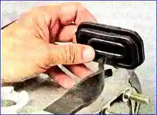
Remove the cover from the lever.
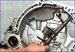
We lift the fork so that its lower part comes out of the hole in the metal bushing pressed into the clutch housing boss, and remove the clutch release fork, bringing the fork lever out through the window in the housing.
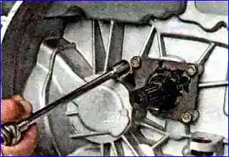
Using a 10mm socket with an extension, unscrew the three bolts securing the guide sleeve to the clutch housing
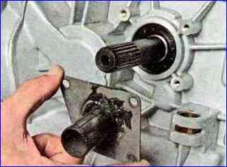
Remove the bushing
We install the parts of the clutch release mechanism in the reverse order.
Apply grease to the inner surfaces of the clutch release fork bushings, as well as to the outer surface of the bearing guide bushing.
Replace the torn rubber cover of the clutch release fork lever with a new one.


