Thermal gaps in the valve mechanism are used to ensure a hermetic fit of the valve on the seat, when the parts of the valve drive expand during engine operation
The value of the thermal gap at the intake and exhaust valves is set the same and is adjustable within 0.25-0.30 mm.
When re-checking the gaps after scrolling the crankshaft of the adjusted engine, it is possible to change them to the limits of 0.20-0.35 mm due to the error in the shape and location of the surfaces of the parts of the gas distribution mechanism, which is acceptable.

If the thermal gaps are too large, the valve lift decreases, as a result of which filling and cleaning of the cylinders deteriorate, shock loads increase and wear of the gas distribution mechanism parts increases.
At very small gaps, as a result of thermal expansion of the parts of the gas distribution mechanism, the valves do not fit tightly to the seats, gas-dynamic processes in the engine cylinders are disturbed, and the power and technical and economic performance of the engine deteriorate.
In addition, reducing the clearance in the exhaust valve drive can lead to overheating of the valves and their burnout.
Thermal clearances should be adjusted on a cold engine or not earlier than 1 hour after it has been stopped.
When adjusting the thermal gaps and re-checking them, it is recommended to press the rocker arms:
- on the head of the right row of cylinders, the rocker arms of the exhaust valves to the end of the axle, the intake valves - to the thrust washer;
- on the head of the left row of cylinders, the rocker arms of the exhaust valves to the thrust washer, the intake valves - to the end of the axle.
The exhaust valves of the right bank of cylinders are located closer to the fan, the exhaust valves of the left row of cylinders are closer to the flywheel.
Adjustment sequence:
- 1. Turn off the fuel supply.
- 2. Loosen the cylinder head cover bolts and remove the covers.
- 3. Check the tightening torque of the rocker axle bolts, which should be 120-150 Nm (12-15 kgf m).
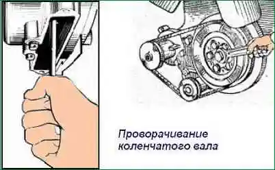
4. Turning the crankshaft clockwise (when viewed from the fan side) in front with a wrench for the pulley fastening bolt or behind with a crank for the flywheel through the hatch in the lower part of the flywheel housing, using the holes in the flywheel (Fig. 2), set the moment when the inlet valve of the first cylinder fully rise (that is, close).
Continuing to rotate the crankshaft, turn it about another ⅓ turn (≈120º).
This position of the crankshaft corresponds to the compression stroke in the first cylinder and both valves of this cylinder will be closed.
5. Check with a feeler gauge the gap between the end of the valve and the toe of the rocker at the intake and exhaust valves of the first cylinder and, if necessary, adjust.
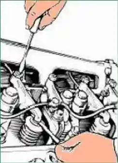
6. To adjust the gaps, unscrew the nut of the adjusting screw, insert the probe into the gap and, turning the screw with a screwdriver (Fig. 3), set the gap to 0.25-0.30 mm.
Hold the screw with a screwdriver, tighten the nut and check the clearance.
With a properly adjusted gap, a 0.25 mm thick probe should enter with light pressure, a 0.30 mm thick one with force.
7. To adjust the valve clearances of the remaining cylinders, turn the crankshaft in the same direction until the intake valve of the regulated cylinder is completely closed and an additional ⅓ turn.
Adjust the gaps as indicated above (see item 6).
It is recommended to adjust the clearances on the cylinders in accordance with the order of their operation.
The order of engine operation by cylinders and the cylinder numbering scheme are given in the article - Main parameters and characteristics of YaMZ-238 engines
8. After adjusting the clearances, start the engine and listen to its work.
There should be no knocks in the valve mechanism.
If there is a characteristic knock of the valves, stop the engine and repeat the gap adjustment.
9. Install and fix the cylinder head covers, check the condition of the gaskets.
Oil should not leak at the place where the covers fit.