By default, we already have the cylinder head removed
We discussed the instructions for removing the head in the article “Removing and installing the cylinder head of a 2.0-liter engine. - G4KD and 2.4 liters. – G4KE”
- 1. Remove flywheel (vehicles with manual gearbox).
- 2. Remove drive plate (vehicles with automatic transmission).
- 3. Remove the engine assembly with the gearbox and install it on a special stand.
4. Remove the timing belt.
5. Remove cylinder head

Disconnect the A/C compressor from the engine (A).

Remove the alternator (A) from the engine.

Remove the power steering pump and bracket.

Remove the tensioner mounting bracket assembly (A).

Remove dipstick assembly (A)

Remove knock sensor (A)

12. Remove the oil pressure sensor (A)

- 13. Remove the crankshaft position sensor (A).
- 14. Remove the water pump.
- 15. Remove the balance shaft module.
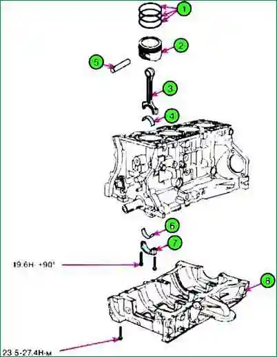
- 16. Remove the crankcase (A).

- 17. Check the axial clearance of the connecting rod.
- 18. Remove the connecting rod cap and check the oil clearance.
- 19. Remove piston and connecting rod assembly.
- (1) Use special tool to remove soot from the upper surface of the cylinder.
- (2) Push the piston, connecting rod, and upper connecting rod bearing shell through the top surface of the cylinder block.
- - Keep bearings, connecting rod and cap together.
- - Place the piston and connecting rod in the correct order.
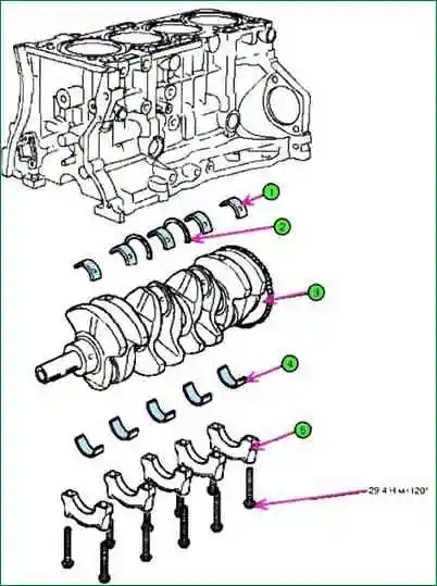
- 20. Remove the crankshaft bearing cap and check the oil clearance.
- 21. Check crankshaft end play.

- 22. Raise the crankshaft off the engine damaging the shaft journals.
- Place the main and thrust bearings in the correct order.
- 23. Check fit between piston and pin.
- Try to move the piston on your finger back and forth. If movement is not possible, replace the piston and pin.
- 24. Remove piston rings.
- - Using a ring expander, remove the 2 compression rings.
- - Manually remove the 2 side rails and gasket.
- Place the piston rings in order
- 25. Disconnect the connecting rod from the piston.
Checking the technical condition of the block and parts of the cylinder block
Connecting rods and crankshaft
1. Check the end play of the connecting rod. Using a feeler gauge, measure the end play by moving the connecting rod forward/back.

Standard gap size: 0.1 - 0.25 mm.
Maximum value: 0.35 mm.
If the axial clearance of the connecting rod exceeds the maximum permissible norm, it is necessary to replace it with a new one.
If, after installing a new connecting rod, the axial clearance exceeds the maximum allowable rate, it is necessary to replace the crankshaft assembly.
2. Measure the clearance in the bearings of the connecting rod journals of the crankshaft.
Make match marks on the connecting rod and the connecting rod cap for proper installation.
Remove the two connecting rod cap nuts.
Remove the connecting rod cap together with the bearing shell.
Clean and wash the crankshaft bearing and crankpin.
- Put a special plastic gauge on the crankpin, along the axis of the crankshaft.
Install the connecting rod cap and tighten the mounting bolts to a torque of 19.6 Nm + 90˚.
Do not rotate the crankshaft.
Unscrew the fastening nuts and remove the connecting rod cap.
Measure the thickness of the plastic gauge (the scale is included with the kit). Standard clearance in bearings: 0.025 - 0.043 mm.

If the plastic gauge is too wide or too thin after removal, remove the top insert and install a new one.
Then repeat the bearing clearance measurement. It is necessary to select the insert according to the color of the marking.
Do not insert a washer or scratch the surface of the clearance adjustment bushing.
- If the clearance in the bearing is still too large or too small, it is necessary to install the next insert and repeat the measurement.
Selection of liners
Crankshaft mark I (1):
- Connecting rod mark - "a (A)", bearing class "D" (yellow);
- Connecting rod label - "b (B)", bearing class "C" (green);
- Connecting rod label - "c (C)", bearing class "B" (none);
Crankshaft mark II (2):
- Connecting rod label - "a (A)", bearing class "C" (green);
- Connecting rod label - "b (B)", bearing class "B" (none);
- Connecting rod mark - "c (C)", bearing class "A" (black);
Crankshaft mark III (3):
- Connecting rod label - "a (A)", bearing class "B" (none);
- Connecting rod mark - "b (B)", bearing class "A" (black);
- Connecting rod mark - "c (C)", bearing class "AA" (blue);
Crank dimensions:
- Class "a", label "A", size 51.00 ~ 51.006;
- Class "b", label "B", size 51.006 ~ 51.012;
- Class "c", mark "C", size 51.012 ~ 51.018
If it is impossible to adjust the clearance in the bearings by selecting liners, it is necessary to replace the crankshaft assembly and repeat the adjustment.
If the identification mark is not visible on the liner due to soot, it must be washed in a solvent. Do not clean the insert with a scraper or wire brush.
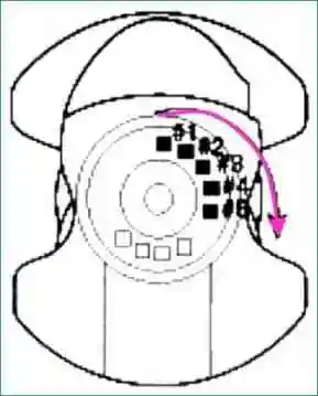
The location of the connecting rod identification mark is shown below.

Read the order of the labels according to the arrow in the figure below.

Crankshaft dimensions
Class - mark number - neck outer diameter, mm:
- I - 1 - 47, 966 ~ 47, 972;
- II -2 - 47.960 ~ 47.966;
- III - 3 - 47.954 ~ 47.960;
Insert dimensions

Label:
Class - label color - insert thickness, mm
- AA - blue - 1.517 ~ 1.520;
- A - black - 1.514 ~ 1.517;
- B - missing - 1.511 ~ 1.514;
- C - green - 1.508 ~ 1.511;
- D - yellow - 1.505 ~ 1.508
3. Measure the clearance in the crankshaft bearings, for this:
- Unscrew the mounting bolts and remove the covers of the main bearings together with the bearing shells.
Clean all main bearings and bearing shells.
Place a special plastic gauge on each crankshaft main journal.
Install all main bearing covers and tighten the mounting bolts to a torque of 29.4 Nm + 120˚
Do not rotate the crankshaft
Remove the cover and bearing again, measure the thickness of the plastic gauge (the scale is attached to the kit). Standard value: 0.025 - 0.043 mm.
Selection of liners for main bearings
Crankshaft marks - hole marks - bearing shell assembly classification:
- I (yellow) - "a (A)" - "D" (yellow)
- I (yellow) - "b (B)" - "C" (green)
- I (yellow) - "c (C)" - "B" (missing)
- II (missing) - "a (A)" - "C" (green)
- II (missing) - "b (B)" - "B" (missing)
- II (missing) - "c (C)" - "A" (black)
- III (white) - "a (A)" - "B" (missing)
- III (white) - "b (B)" - "A" (black)
- III (white) - "c (C)" - "AA" (blue)
If the measurement value is too large or small, remove the upper half of the bearing, install a new one, select the bearing according to the color of the mark, recheck the clearance.
Do not grind or scratch bearings or caps to adjust clearance.
Cylinder block

Class - label - inner diameter of the main bearings of the crankshaft, mm:
- a - A - 56,000 ~ 56,006;
- b - B - 56.006 ~ 56.012;
- c - C - 56.012 ~ 56.018
If the gauge shows that the clearance is still not standard, try installing a larger or smaller bearing and check the clearance again.
If it is impossible to adjust the clearance in the bearings by selecting liners, it is necessary to replace the crankshaft assembly and repeat the adjustment.
If the identification mark is not visible on the liner due to soot, it must be washed in a solvent. Do not clean the insert with a scraper or wire brush.
When installing, make sure that the number marked on the connecting rod and its cap matches the cylinder number.
When installing a new connecting rod, make sure that the tabs for fixing the liner match the grooves on the liner.
Replace the connecting rod assembly if its side surface is damaged. Also, replace the connecting rod, with increased wear of its working parts.
Using special equipment, measure the bend and twist of the connecting rod.
The allowable amount of bending of the connecting rod is 0.05 mm / 100 mm. The allowable amount of twisting of the connecting rod is 0.1 mm / 100 mm.
If the allowable bending and twisting values are exceeded, the connecting rod assembly must be replaced.
The location of the marks characterizing the inner diameter of the main bearings of the crankshaft:
Crankshaft dimensions (main journals)
Class - label color - main journal outer diameter, mm:
- I - yellow - 54.956 ~ 54.962;
- II - missing - 54.950 ~ 54.956;
- III - white - 54.944 ~ 54.950
Main bearing shell dimensions

Location of identification marks on the main bearing bushing
Class - label color - insert thickness, mm:
- "AA" - blue - 2.026 ~ 2.029;
- "A" - black - 2.023 ~ 2.026;
- "B" - missing - 2.020 ~ 2.023;
- "C" - green - 2.017 ~ 2.020;
- "D" - yellow - 2.014 ~ 2.017
Check the end play of the crankshaft.
Using a dial gauge, measure the end play of the crankshaft by moving it forward/backward with a screwdriver.

Standard value of axial clearance: 0.06 - 0.26 mm. Maximum permissible value: 0.30 mm.
If the axial clearance exceeds the allowable limit, the thrust bearings must be replaced. Thrust bearing thickness: 1.925-1.965 mm.

Using a micrometer, measure the outside diameter of the crankshaft journals and crankpins. diameter of the main journals of the crankshaft: 51.942-51.960 mm. diameter of the connecting rod journals of the crankshaft: 47.954-47.972 mm.
Measure in two mutually perpendicular planes, as shown in the figure.