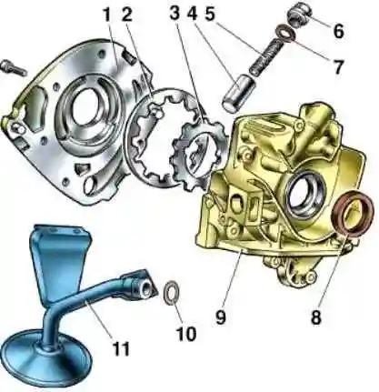
Oil pump - gear type, with internal gears and pressure reducing valve
The drive is carried out from the toe of the crankshaft.
The drive gear (smaller diameter) is mounted on two flats on the front end of the crankshaft.
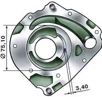
The maximum diameter of the socket for the driven (large) gear when worn should not exceed 75.10 mm, the minimum width of the segment on the body separating the drive and driven gears is 3.40 mm.
The axial clearance should not exceed 0.12 mm for the drive gear and 0.15 mm for the driven gear.
Usually the pump is removed during engine repair, less often when the pump performs poorly.
Execution:
Remove the crankshaft position sensor, to do this:
Prepare the car and disconnect the negative terminal of the battery

Disconnect the crankshaft sensor connector

Use a 10mm wrench to unscrew the sensor mounting bolt

Remove the sensor from the hole in the boss on the oil pump body
- - Remove the generator drive pulley (see How to check and replace the timing belt on a VAZ-21114 engine)
- - Remove the oil pan
- - Remove the oil receiver (see How to remove and install the oil receiver of a VAZ-21114 engine)

Using a 10mm socket, unscrew the six bolts securing the oil pump to the cylinder block.

Use a screwdriver to pry up the pump housing by the lugs

Removing the oil pump

Remove the oil pump gasket

Clamp the pump in a vice with soft metal jaw linings.
Use an 8mm hex to unscrew the pressure reducing valve plug

The plug is sealed with an aluminum ring.

Remove the spring and piston of the pressure reducing valve

Use a 5mm hexagon to unscrew the six screws securing the cover to the pump body.

Remove the pump cover and remove the driven and drive gears.
We wash the parts with oil pump and check their technical condition - the diameter of the socket for the driven gear, the width of the segment on the body, the axial clearances of the gears.
When assembling the pump, lubricate the surface of the outer diameter of the oil seal with engine oil and press it into cover 9 until it stops.
Carefully secure the cover in a vice, install the gears with chamfers on the tops of the teeth inside the housing 1 and tighten the screws securing the housing and cover.
Insert the pressure reducing valve, spring and tighten the valve plug, installing an aluminum O-ring 7 (1.5±0.2) mm thick under the plug.
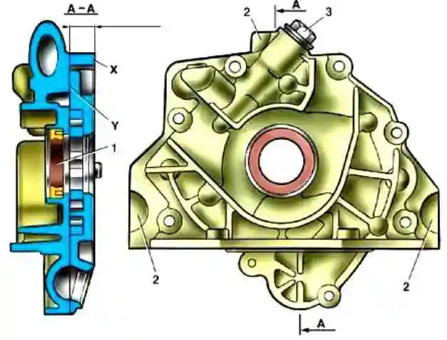
The aluminum cover, when checking it in the contact area of the gears, should not have ledges, the surface of the cover should be flat.
If there is noticeable wear, clamp the cover at points 2 and mill the X and Y surfaces to size (13.5±0.3) mm.
The maximum metal removal should not exceed 0.2 mm.
Replace crankshaft oil seal 1 with a new one and press in until it stops.
When pressing the oil seal, the force should be applied as close as possible to the outer diameter of the oil seal.
The working surfaces of the pump housing must not be scratched.
The maximum diameter of the socket for the driven gear must not exceed 75.10 mm.
The minimum segment width must be at least 3.40 mm.
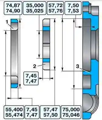
Main dimensions of new pump parts
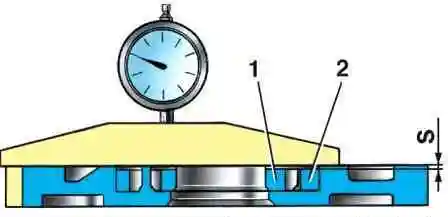
Measure the maximum axial clearances with an indicator, which should not exceed 0.12 mm for the drive gear and 0.15 mm for the driven gear.
If the clearances exceed the limits, replace the gears.
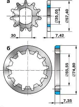
Limit wear of gears. If their dimensions exceed the limit values, also replace the gears.
Before assembling the pump, be sure to lubricate the drive and driven gears, the housing in the gear area, the rubber O-ring of the oil receiver tube and the pressure reducing valve with engine oil
")

")
")
")
")
")
")
")