Proper operation of the gearbox and its service life are directly dependent on the culture of operation, so you need to carefully consider all routine maintenance provided for in this manual
The use of lubricants other than those recommended in this manual is not permitted.
In order to avoid damage to the range synchronizer and the main gearbox synchronizers, shifting gears in the main box with the range switch indicator lamp on is not allowed.
In order to avoid an excessive increase in the engine speed and increased wear of the gearbox synchronizers, do not allow the lower range to be turned on in the demultiplier at a vehicle speed above 45 km / h.
In order to avoid damage to the gearbox when the car is moving, it is strictly forbidden to engage the first gear when the upper range of the demultiplier is on.
Characteristics of YaMZ-239 gearboxes
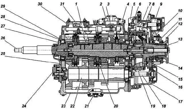
The YaMZ-239 gearbox manufactured by Avtodizel OJSC (base model, Fig. 1) is a nine-speed mechanical gearbox, consists of a five-speed main gearbox and a dual-range planetary demultiplier, with synchronizers in all gears, except for first gear and reverse gear.
The main differences between the modifications and configuration of the gearbox from the base model
The ASBP relay is designed in such a way that it allows the inclusion of the lower range at a frequency of rotation of the output shaft of the gearbox no more than 1000 min-1, which, depending on the gear ratios of the drive axle, transfer case, wheel rolling radius corresponds to a vehicle speed of 25 - 45 km/h.
The filling capacity of the gearbox lubrication system is 9.5-11.5 liters, depending on the angle of inclination of the longitudinal axis of the power unit (gearbox) on a particular vehicle.
The oil filler hole is located on the right side of the spacer installed between the crankcases of the main box and the demultiplier.
The oil level is determined by the lower edge of this hole.
Operation of the YaMZ-239 gearbox
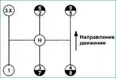
Shift gears from first to fifth and from sixth to ninth, as on any gearbox, by moving the shift lever to the appropriate position.
To engage sixth gear, leave fifth gear engaged and move the range switch button to high range in the range.
(The location of the range control controls is indicated in the instruction manual for the car).
Sixth gear is engaged by moving the shift lever of the main gearbox to the 2nd gear position.
At the moment the lever passes through the neutral position, the highest range in the demultiplier is automatically switched on, while the lever is held in the neutral position until the indicator lamp for switching the demultiplier goes out (that is, until the high range is turned on).
To switch from sixth to fifth gear, move the range switch button to the lower range when sixth gear is engaged, while the vehicle speed should not exceed 45 km / h.
Then, shift the gear lever to neutral, hold until the indicator lamp goes out, and shift into fifth gear in the main box.
When controlling the gearbox using a mechanical remote drive, the positions of the gear lever handle may differ from those shown in the diagram (Fig. 2) and are indicated in the vehicle manual.
When shifting the shift lever from neutral to reverse, you should feel the resistance of the spring guard.
Turn on reverse only after the car has come to a complete stop.
Reverse should be carried out with the lower range turned on in the demultiplier.
Starting off a loaded vehicle is carried out in first gear. Starting off in second gear is allowed only on paved roads with a partial load of the car.
Rules for towing a car
Towing a vehicle with the engine off can only be done with the cardan shaft disconnected.
Oils and lubricants
Recommended gear oils should be used to lubricate the gearbox.
Oil level below the control hole is not allowed.
To lubricate parts of the clutch release mechanism, use SHRUS-4M lubricants TU 38401-58-128-95 or SHRUS-4 TU 0254-001-05766076-98.
MAIN DIFFERENCES OF THE MODIFICATIONS AND OPTIONS OF THE GB FROM THE BASIC MODEL
KP model. Main differences from the basic CP model
- YaMZ-239-02 Equipped with parts for the installation of a non-contact speedometer sensor
- YaMZ-239-03 Equipped with a direct gear lever instead of a mechanism for a remote drive
- YaMZ-239-04 Equipped with a mechanism for remote drive with an increased reach of the mechanism shaft
- YaMZ-2391 Has modified gear ratios of 5 and 9 gears, equipped with a gear for power take-off from the right side hatch of the crankcase of the main box
- YaMZ-2391-02 Equipped with a mechanism for remote drive with an increased reach of the mechanism roller
- YaMZ-2391-10 Has gear ratios and power take-off like a gearbox
- YaMZ-2391 and a gearshift lever like a gearbox YaMZ-239-03
- YaMZ-2393-01 Does not have a speedometer drive unit
- YAMZ-2393-03 Does not have a speedometer drive unit, the demultiplier is equipped with a special cardan shaft mounting flange (without end slots)
Gear ratios of YaMZ-239 gearboxes

The range switching mechanism of the demultiplier is equipped with an automatic low range locking system (ASBP).
Maintenance of the YaMZ-239 gearbox
The types and frequency of maintenance of the gearbox correspond to the types and frequency of maintenance of the engine.
Maintenance after the break-in of the car:
After running the car, change the oil in the gearbox housing, clean the oil intake screen and the drain plug magnet from the run-in products.
First maintenance (TO-1):
- 1. Check the oil level in the crankcase and top up if necessary.
- 2. Check the operation of ASBP nodes. The low range in the gearbox should not be engaged at a vehicle speed corresponding to an output shaft speed of more than 1000 min -1 .
Second maintenance (TO-2):
- Perform all operations of the first maintenance TO-1.
- Check and, if necessary, adjust the rear gearbox support in accordance with the vehicle manual (if the support is provided for by the vehicle design).
- Clean and lubricate the gearbox air distributor parts (using grease No. 158 according to TU 38.101.320-77. Litol 24 is allowed).
- Clean and lubricate the cuffs, piston and walls of the changeover cylinder.
- Fix air leaks and all malfunctions in the pneumatic system of the range control mechanism.
- Each time the gearbox is disconnected from the engine, fill the input shaft front bearing installed in the flywheel with Litol 24 GOST 21150 grease. At the same time, check the axial play of the gearbox shafts, which should be no more than 0.1 mm.
If the backlash is more than the specified values, then they must be adjusted according to the instructions below or the bearings must be replaced.
Change the oil in the gearbox with flushing the crankcase, mesh and magnet, depending on the operating conditions, according to the following scheme:
- cars with an annual mileage of 80 thousand km or more - after 50 thousand km;
- vehicles with an annual mileage of less than 80 thousand km and under severe operating conditions (dirt roads, mountainous terrain or hot, dry climatic region, etc.) - after 30-40 thousand km.
Drain the gearbox oil immediately after hot work. Flush the gearbox with industrial oil I-12A or I-20A in accordance with GOST 20799-88, for which:
- 5.5-6 l pour it into the crankcase of the box;
- set the gear lever to neutral, start the engine for 7-8 minutes, then stop it, drain the flushing oil and refill with fresh oil.
It is strictly forbidden to flush the gearbox with kerosene or diesel fuel in order to avoid failure of the oil pump due to insufficient suction vacuum and, as a result, failure of the gearbox.
In case of a complete overhaul of the gearbox, lubricate the oil pump with the oil used in the gearbox before installation.
The procedure for installing the shafts in the gearbox housing and adjusting the tapered bearings
Measurements of all sizes to determine the required number of mounting and adjusting shims must be made with an accuracy of 0.01 mm at least in three places equidistant from each other.
When calculating the total thickness of these gaskets, the arithmetic mean of these dimensions should be taken.
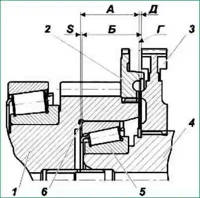
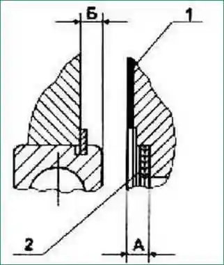
- 1. Select the required number of mounting gaskets to ensure the relative position of the primary and secondary shafts with mounting dimension D=0.3 mm (Fig. 3), for this:
- 1.1. With the inner ring of the front bearing of the output shaft pressed to the stop, measure dimension “B” (from the end of the synchronizer hub to the wide end of the outer ring of the bearing).
Before measuring, press the bearing ring firmly against the rollers and rotate it for at least five turns.
- 1.2. With the gear ring pos. pressed all the way to the end of the input shaft. 2 measure dimension “A” (from the end of the gear ring to the end of the undercut for the bearing in the input shaft).
- 1.3. Select the required number of mounting gaskets based on the condition: Spr=S+(0-0.05), where Spr is the total thickness of the gaskets, and S=A+0.3-B
Set the selected gaskets in the bore to the end of the input shaft.
- 2. Insert the assembled intermediate and secondary shafts into the gearbox housing and fix their mutual position relative to each other using a technological device (Fig. 4) in such a way that the mounting dimension “A” is provided (from the front end of the gearbox housing to the front end of the hub intermediate shaft drive gears) equal to 48 ± 0.025 mm and mounting dimension "B" (from the front end of the gearbox housing to the front end of the synchronizer hub 4-5 gears) equal to 90.3 ± 0.025 mm.
In this case, the blocking ring pos. 4 and clutch pos. 5 synchronizers must be fixed on the output shaft hub, and the outer ring of the front bearing of the intermediate shaft must be removed.
- 3. After completing the work according to paragraph 2, select the required number of mounting gaskets to ensure a backlash-free end stop of the rear bearing of the intermediate shaft with a spacer and the seat of the rear bearing of the output shaft with the gear coupling of the demultiplier.
Select mounting gaskets as follows:
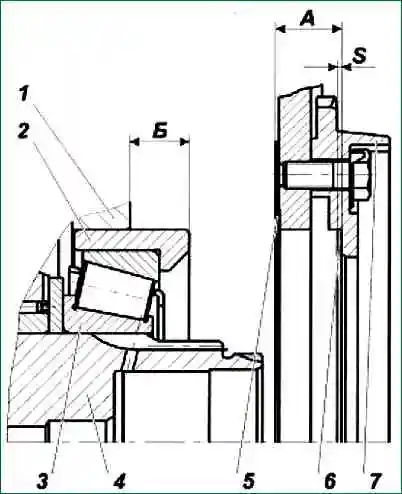
- 3.1. Measure the absolute values of the dimensions "A" (between the ends of the sealing gasket and the spacer) and "B" (between the ends of the crankcase and bearing) fig. 5.
In this case, the end of the hub of the intermediate shaft drive gear must be tightly (under the force of the own weight of the shaft) pressed against the end of the technological device, and the outer ring of the rear bearing against the rollers.
- 3.2. Select the required number of mounting gaskets based on the condition: Spr=S±0.05, where Spr is the total thickness of the gaskets, and S=A-B-0.12; 0.12 - deformation of the gasket.
Set the selected gaskets in the bore ku to the end face of the demultiplier spacer.
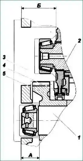
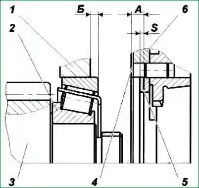
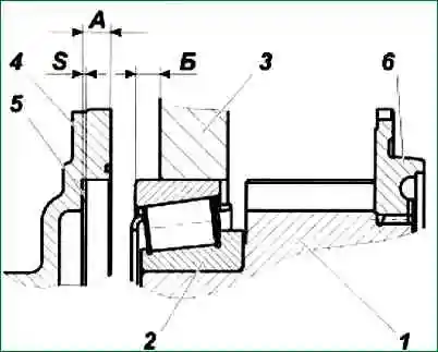
3.3. Measure the absolute values of the dimensions "A" (between the ends of the gear coupling and the seal) and "B" (between the ends of the crankcase and the bearing seat) fig. 6.
At the same time, the end of the synchronizer hub of 4-5 gears should be tightly (under the force of the own weight of the shaft) pressed against the end of the technological device, and the outer ring of the rear bearing with the socket should be pressed against the rollers.
3.4. Select the required number of mounting gaskets based on the condition: Spr=S±0.05, where Spr is the total thickness of the gaskets, and S=A-B-0.12; 0.12 - deformation of the gasket.
Install the selected gaskets in the bore to the end face of the range gear clutch.
- 4. Dock the demultiplier with mounting gaskets selected according to paragraph 3 to the gearbox housing, ensuring that the bolts for fastening the demultiplier to the gearbox are tightened with Mcr = 215.74-274.5 Nm (22-28 kgf m). Before installing the demultiplier on the sealing gasket pos. 5 (fig. 7) on both sides, apply sealant UG-9 TU 6-01-1326-86 or UG-6 TU 6-01-1285-84 with a continuous strip 2-3 mm wide along the contour.
- 5. Dismantle the technological device, and then adjust the axial clearances in the bearings of the intermediate, primary and secondary shafts.
Adjust as follows:
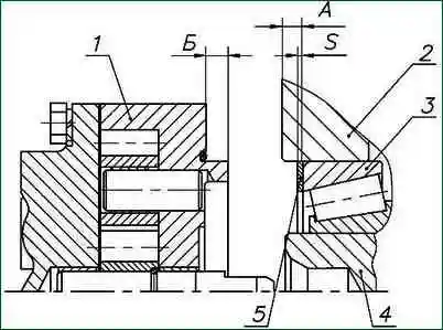
- 5.1. Install the outer ring of the front bearing of the intermediate shaft into the bore of the gearbox housing, and then measure the absolute value of the dimension "A" (between the ends of the housing and the outer ring of the bearing) fig. 8.
At the same time, the outer ring of the rear bearing of the intermediate shaft should be tightly (under the force of the own weight of the shaft) pressed against the end face of the demultiplier spacer, and the outer ring of the front bearing - to the rollers.
Turn the layshaft at least five turns before measuring.
- 5.2. Measure the absolute value of dimension B (between the ends of the oil pump housing).
- 5.3. Select the required number of shims based on the condition: Spr=S (0.005-0.05), where Spr is the total thickness of the shims, and S=A-B.
Place the selected gaskets into the bore of the gearbox housing to the end of the outer ring of the bearing.
- 5.4. Dock the oil pump to the gearbox housing, ensuring that the bolts securing the oil pump to the gearbox housing are tightened with Mcr = 23.53-35.30 Nm (2.4-3.6 kgf m).
- 5.5. Check the correct adjustment of the intermediate shaft bearings by moving it axially. The axial movement of the shaft must be within (0.005-0.06).
Install the input shaft assembly into the bore of the gearbox housing with gaskets selected according to paragraph 1. fig. 8.
Make sure that the countershaft bearings are "not overtightened" and that the shaft is free to turn by turning the input shaft by hand by the splined end a few turns.
If the results of the bearing adjustment check are unsatisfactory, remove the oil pump and re-adjust.
- 5.6. Measure the size "B" fig. 8, (between the ends of the gearbox housing and the outer ring of the bearing), in this case, the socket of the rear bearing of the secondary shaft must be tightly (under the force of the own weight of the secondary shaft) pressed through the mounting gaskets to the end of the range gear clutch; the input shaft must be tightly (under the force of its own weight) pressed through the mounting gaskets to the end of the outer ring of the front bearing of the secondary shaft, and the outer ring of the rear input shaft bearing - to the rollers.
- 5.7. Measure the absolute value of dimension "A" (between the ends of the input shaft bearing cap).
- 5.8. Select the required number of shims based on the condition: Spr = S-(0.005-0.05), where Spr is the total thickness of the shims, and S=A-B.
Install the selected gaskets into the bore of the input shaft bearing cap to the end.
- 5.9. Dock the input shaft bearing cover to the gearbox housing, ensuring that the bolts securing the cover to the crankcase are tightened with Mcr (23.53-35.30) Nm [(2.4-3.6) kgf m].
- 5.10. Check the correct adjustment of the bearings of the primary and secondary shafts by axially moving one of the shafts, as well as turning the input shaft at a speed of 10-15 min -1, while the synchronizer clutches and the first gear and reverse clutch must be in the neutral position, the locking rings must be wrung out from the cones of the gear couplings.
The axial movement of the shafts should be within (0.005 ... 0.06), and the moment of scrolling the input shaft should be no more than 2-3 Nm (0.2-0.3 kgf m).
If the results of the bearing adjustment check are unsatisfactory, remove the input shaft bearing cover and re-adjust.
Requirements for the assembly of the gearbox and its components
The parts and assemblies of the gearbox entering the assembly must be clean, traces of corrosion and scale are not allowed. Oil and air passages in parts must be flushed and purged.
Release units and parts from packaging, transport plugs only before installation on the gearbox.
When assembling, ensure the preservation of components and parts from damage. The use of steel drifts is not allowed.
When installing bearings on shafts, apply the load to the inner rings. Impact loading during installation and dismantling of bearings is not allowed.
When installing sealing gaskets, wrinkles, tears, overlapping of connecting channels with gaskets are not allowed.
Lubricate all friction surfaces of gearbox parts, including friction surfaces of shift mechanism parts, raceways of gear bearings, when assembling with a thin layer of oil used to break in the gearbox.
Syringe the clutch bearing and the clutch release shaft bushing through the grease fittings with Litol-24 GOST 21150 grease until it appears from under the clutch bearing deflector and from the gaps of the bushings.
Lubricate the guide of the cover under the coupling and the working edge of the cuff of the input shaft with a thin layer of the above grease.
The gears of the gearbox must be assembled in accordance with the requirements.
Installation of gears on shafts must be carried out in accordance with the requirements of the documentation.
When pressing the gears onto the intermediate shaft, grinding and scratching on the surfaces of the gear holes and the shaft are not allowed. The pressing force of the gears at the initial stage is 25-35 kN (2550-3570 kgf).
The temperature of the intermediate shaft with gears pressed onto it before installation in the gearbox should not exceed 35 ° C. Cool if necessary in the air.
Gearbox assembly features
Tighten the bolts of the crankcase fastening in two stages, article - Tightening torques for threaded connections YaMZ-238
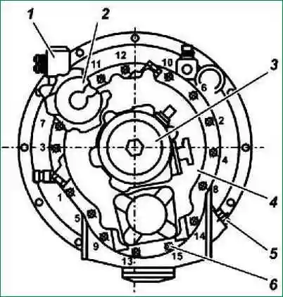
Tightening sequence according to fig. 10.
When repairing the range-switch with the replacement of synchronizer parts, adjust the required rod stroke when the higher range is turned on, ensuring that the fork bearings are unloaded at the higher range, for which:
- - Enable the highest range in the demultiplier with the adjusting bolt pos. 6 (Fig. 1), by supplying air under pressure from 784 to 833 kPa (8-8.5 kgf / cm 2) into the pneumatic cylinder.
- - Verify that the high range engagement gear clutches are fully engaged. When fully engaged, the indicator lamp should go out, the propeller shaft mounting flange should not turn by hand.
- - Screw the adjusting bolt all the way into the piston rod, tighten 5/6 of a turn. Repeat this operation several times, and if the position of its faces remains unchanged when turning the bolt, lock the bolt with a lock nut, tightening it with a torque of 137 to 157 Nm (14 to 16 kgf m).
When properly adjusted, the flannel The center of the output shaft must turn without jamming from the effort of the hand.
Incorrect adjustment leads to accelerated wear of the shift fork bearings.