Since September 2004, Avtodiesel OJSC has switched to equipping YaMZ engines that meet Euro-1 and Euro-2 requirements with fan drives equipped with an electromagnetic switch
Electromagnetic switch
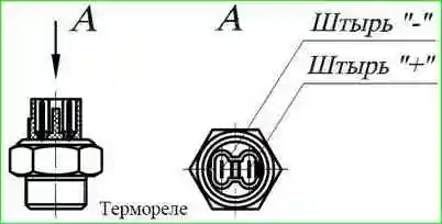
Features of the operation of the electromagnetic switch (Fig. 1-4) are that the thermal switch located on the right water manifold sends an electrical signal to the solenoid valve, which is installed directly on the fan drive housing and controls the flow of oil into the drive clutch.
The connection between the valve and the body is sealed with a paronite gasket.
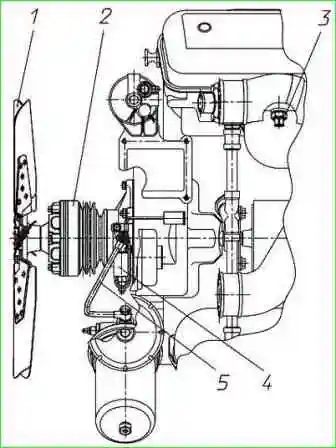
Since August 2007, the oil supply to the solenoid valve has been carried out from the oil filter housing through the oil supply pipe 5 (Fig. 1).
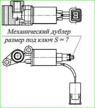
The design of the solenoid valve (Fig. 2) provides the necessary oil pressure when the fan is turned on, and also provides for a controlled supply of oil in the off state through a special self-cleaning jet to ensure lubrication of the drive bearings.
When there is no voltage on the contacts of the plug socket, the solenoid valve is in the closed position.
The valve opens when 24 V is applied.
The operation of the solenoid valve is controlled by a three-position switch located in the driver's cab.
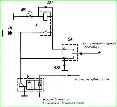
When the fan is turned on, the control lamp on the driver's console lights up (see the diagram in Fig. 3).
The circuit for switching on the fan clutch is electrical, in principle (Fig. 11) includes the following elements:
Element designation - name - (quantity)
- BK - thermal switch 661.3710-01 - (1)
- Y - solenoid valve KEM 32-23* - (1);
- HL - control lamp - (1);
- SA - switch 51.3709** - (1);
- VD1 VD2 - Diode D247A** - (2);
- K - Relay 11.3747** - (1)
* - The fan drive is equipped with a KEM 32-23 solenoid valve with an on-board network voltage of 24 V.
** - The electrical circuit diagram, therefore, it can be modified, including other components that are selected by enterprises-consumers of power units.
Functions of the elements of the electrical circuit diagram:
- The SA switch is located in the cockpit.
- The SA switch has three positions:
- "Disabled" - the fan is turned off regardless of the engine temperature.
- "Enabled" - the fan is on regardless of the engine temperature.
- "Automatic" - the fan is turned on by a thermal relay depending on the temperature of the engine.
- HL - control lamp, turns on when the fan is running.
In case of failure of the electrical part of the fan control system (breaks in the winding of the electromagnet, wires, etc.), the design of the KEM 32-23 solenoid valve provides for forced switching on of the fan using a mechanical backup.
The valve is opened by tightening the doubler screw until it stops.
When changing the fan operation modes with a three-position switch located in the driver's cab, the screw of the mechanical override must be turned out as far as it will go.
Attention! When the fan is operating in automatic mode (the fan is switched on by the electrical signal of the thermal relay, depending on the temperature), the screw of the manual override must be screwed in until it stops.
Solenoid valve KEM 32-23M
Since September 2006, Avtodiesel OJSC has been completing YaMZ engines that meet the requirements of Euro-1 and Euro-2 environmental standards with fan drives equipped with a KEM 32-23M solenoid valve, which is structurally similar to the KEM 32-23 valve, in order to increase the efficiency of its work to eliminate clogging in the valve body contains a permanent magnet to trap metal particles.
During operation, maintenance of the solenoid valve is not required; if necessary, the magnet can be cleaned from metal particles.