Before installing the demultiplier with a spacer on the crankcase of the main box and the spacer on the crankcase of the demultiplier, apply the anaerobic sealing compound UG-6 TU 6-01-1285-84 to the gaskets on both sides with a continuous strip 2-3 mm wide along the contour
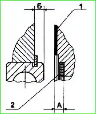
When installing the input shaft bearing cover (Fig. 1), the range gear with spacer on the main box housing (Fig. 2), the rear bearing cap of the range output shaft (Fig. 3), ensure minimum axial play of the shafts using shims, selected as follows:
Measure the dimension "A" of the depth of the groove for the bearing in the bearing cap, taking into account the thickness of the gasket, with an accuracy of 0.1 mm (Fig. 1).
Measure dimension "B" from the end of the outer ring of the bearing to the surface of the crankcase wall with the bearing pressed to the stop with an accuracy of 0.1 mm.
Select the total nominal thickness of shims S from the condition: S = [A - B - (0.2-0.3)] mm
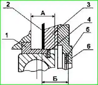
Measure dimension "A" (fig. 2) from the end of the outer ring of the bearing to the surface of the crankcase with an accuracy of 0.1 mm, making sure that the centering ring is pressed in to the stop, and the spring ring and bearing are firmly pressed against the central ring.
Measure the dimension "B" of the depth of the groove for the bearing in the gear coupling, taking into account the spacer and the groove with an accuracy of 0.1 mm.
Select the total thickness of the shims S from the condition S = [B - A - (0.2-0.3)] mm
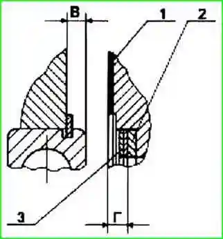
Measure dimension ″B″ (Fig. 3) from the end of the outer race of the bearing to the surface of the crankcase with an accuracy of 0.05 mm, making sure that the spring ring and bearing are firmly pressed against the surface of the crankcase.
Measure the dimension ″Г″ from the gasket to the thrust ring in the undercut of the cover with an accuracy of 0.05 mm.
Select the total nominal thickness of the shims S from the condition: S = [D - V - (0.15-0.2)] mm
Tighten the bolts for fastening the crankcase in two stages (see the table "Tightening torques").
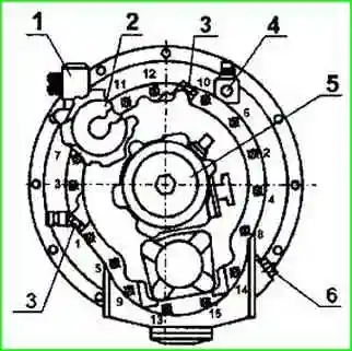
Tightening sequence according to fig. 4.
When repairing the demultiplier with the replacement of synchronizer parts, adjust the required rod stroke when the higher range is turned on, ensuring that the fork crackers are unloaded when operating at the highest range, for which:
1. Engage the high range in the demultiplier by supplying air under pressure from 784 to 833 kPa (8-8.5 kgf / cm 2 ) into the rear cavity of the pneumatic cylinder, make sure that the high range engagement clutches are fully engaged .
When fully engaged, the indicator lamp should go out. The propeller shaft mounting flange should not turn by hand.
2. Screw the adjusting bolt into the piston rod until it stops (when turning the bolt, an increase in resistance to rotation should be felt).
Repeat the operation several times, making sure that the stop is felt at the same position of the bolt head.
3. Turn the adjusting bolt from the position of its stop to the end by one turn (5 faces of the head) and, holding it in this position, lock it with a lock nut, tightening it with a torque of 137-157 Nm (14-16 kgf cm).
After adjustment, the driveshaft mounting flange should turn easily without jamming, by hand. Turn the flange through an angle of at least 360˚.
Attention! Incorrect adjustment causes an overload of the crackers of the range fork, which leads to their rapid destruction.
4 Installation of the range changer on the gearbox run with the axes of the shafts of the main gearbox in a vertical position.
The output shaft of the demultiplier must be turned by hand with any range engaged and gears disengaged in the main box.
Possible malfunctions of the YaMZ-238VM gearbox and how to eliminate them
Fault Remedy
Difficulty shifting
Incomplete clutch disengagement (clutch "leads"):
- - Adjust the free play of the clutch pedal or, if the defect is due to a malfunction of the clutch parts, replace the damaged parts
- - Synchronizer worn or damaged - Replace defective synchronizer
- - Gear teeth damaged - Replace damaged parts
Increased noise during gearbox operation
Insufficient oil in the gearbox - Fill oil up to the level of the control hole
Worn transmission shaft bearings - Replace defective bearings
Increased gear tooth wear - Replace worn gears
Spontaneous disengagement of gears when the car is moving
Uneven wear of gear teeth - Replace defective parts
Increased wear on gearbox shaft bearings - Replace defective bearings
Faulty shift rod locks - Replace faulty parts
Spontaneous switching off of ranges in the demultiplier
Compressed air entering the cylinder cavity opposite to the engaged gear - Replace the defective o-rings of the spool and the intake valve of the air distributor
Increased wear on the fork lugs - Replace the lugs and adjust the stroke.
Non-activation or delayed inclusion of ranges in the demultiplier with the neutral position of the main gear lever
- The indicator lamp does not go out for a long time, air exits through the breather of the air distributor
Inlet valve rubber wear - Replace worn valve
Inlet valve spring broken - Replace defective spring
Worn inlet valve O-ring - Replace O-ring
Irregular fit of the inlet valve to the body - Replace defective parts
Inlet valve sticking in the out position - Clean and lubricate the inlet valve stem, polish if necessary
Worn or hardened seals of the piston of the working cylinder - Replace the seals of the piston
Non-activation or delayed inclusion of ranges in the demultiplier when the lever is in neutral position
- The indicator lamp does not go out for a long time, air escapes through the breather of the top cover
Damage diffuser diaphragm - Replace damaged diaphragm
Worn or hardened O-rings of the slave cylinder in the hole for the shift fork rod - Replace the O-ring
Air passage through the air distributor breather with the gear engaged in the main box
Intake valve rubber wear - Replace valve
Loose fit of tappet to inlet valve - Replace faulty parts