")
")
")
")
")
")
The engine cooling system (fig. 1) is liquid, circulating, including a water pump, a liquid-oil heat exchanger, a fan, thermostats
In addition, the cooling system includes a water cooler, an air-to-air aftercooler and a remote thermometer mounted on the vehicle.
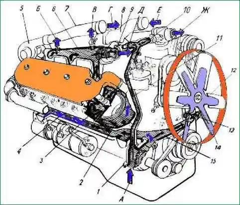
Scheme of the cooling system: 1 - water pump: 2 - cavity of the sleeve cooling unit; 3 - water cavity in the block head; 4 - longitudinal water channel; 5 - turbocharger; 6 - right water pipe; 7 - connecting pipe; 8 - inlet pipe; 9 - thermostat; 10 - tee with connecting pipes; 11 - bypass tube; 12 - plug; 13 - inlet pipe of the liquid-oil heat exchanger; 14 - fan; 15 - transverse water channel; A - coolant supply from a water radiator; B - to the cabin heater; B - air outlet; D - charge air supply to the air-to-air cooler; E, W - to the radiator; E - from the air-to-air charge air cooler to the cylinders
During engine operation, the circulation of coolant in the cooling system is created by a centrifugal pump.
From the water pump 1, the liquid enters the transverse channel 15 and further along the right longitudinal channel 4 into the water cavity of the right row of cylinders, and into the left row of cylinders through the inlet pipe of the liquid-oil heat exchanger 13, cooling the oil in two elements, then into left longitudinal channel.
In order for the coolant to pass through the liquid-oil heat exchanger, a plug 12 is pressed into the front cover of the distribution gears.
Further, the coolant from the water cavities of the cylinders through the guide channels enters the cylinder heads to the most heated surfaces - the exhaust channels and nozzle cups and then collects in the catchment pipes 6.
When a cold engine is heated, the channels connecting the water collection pipes to the radiator are blocked by thermostat valves 9.
The coolant circulates through a tee with connecting pipes 10 and a bypass pipe 11 to the water pump, bypassing the radiator, which speeds up the engine warm-up.
When the coolant reaches a temperature of 80˚ C, the thermostat valves open, the heated liquid enters the water radiator, where it gives off heat to the air flow created by fan 14, and then goes back to the water pump.
When the coolant temperature drops, the thermostats automatically direct all of the coolant flow directly to the water pump, bypassing the radiator.
Thus, by means of thermostats, the optimal thermal regime of the engine is ensured.
Water pump
The centrifugal type water pump is mounted on the front wall of the cylinder block and is driven by a V-belt from a pulley mounted on the front end of the crankshaft.
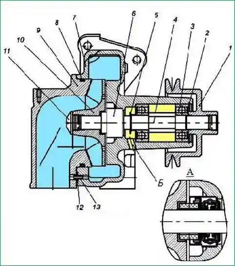
The design of the water pump is shown in Figure 2. In the cast-iron casing 7 of the pump, the impeller 10 pressed onto the roller 4 rotates, creating a flow of coolant.
The pump shaft is mounted on two ball bearings 3 with a one-sided seal.
When assembling the pump, the bearing cavity is filled with grease Litol-24 GOST 21150-87 for the entire life of the pump without additional lubrication.
The seal of the pump bearing cavity is carried out by a mechanical self-clamping seal.
To control the tightness of the mechanical seal, there is a drain hole "B" in the pump housing. Drive pulley 1 is pressed onto the pump shaft.
The water pump is marked on the body 236-1307010-B1.
For water pump repair, see the article "MAZ water pump repair".
Cooling system maintenance
To ensure the normal operation of the engine, the following requirements must be met:
- 1. Fill the cooling system with recommended special anti-freeze fluids or, in exceptional cases, for a short time with clean soft water.
- 2. Pour coolant through a funnel with a mesh, using clean dishes.
- 3. Monitor the temperature of the coolant, keeping it within 75 - 90ºС.
- 4. To avoid the appearance of deformations of the cylinder heads and jacket, add coolant to the cooling system of a warm engine gradually and always during its operation.
- 5. If the cooling system is filled with water, then regularly flush the cooling system with clean water using a special flushing gun, and if it is not available, with a strong stream of clean water, preferably pulsating.
Systematically remove scale from the cooling system.
- 6. When using Antifreeze as a coolant, it is necessary to periodically monitor its color.
If "Tosol" acquires a red-brown color, then this indicates its aggressiveness in relation to the structural materials of engine parts.
In this case, "Tosol" must be replaced by flushing the cooling system before that.

7. Monitor the health of the mechanical seal of the water pump impeller, bearing in mind that the coolant seeping into the water pump bearings damages them.
A malfunction of the mechanical seal is indicated by water leaking from the drain hole (Fig. 3) on the water pump housing, which must not be clogged.
A pump with a bad seal needs to be repaired.
8. In case of violation of the temperature regime, check the serviceability of the thermostats and their gaskets.
The opening temperature of the main thermostat valve should be 80 ± 2ºС (indicated on the thermostat housing).
The valve must open fully, moving at least 8 mm from its seat. Replace the defective thermostat with a new one.
9. To avoid defrosting of the radiator, when operating in winter conditions, the engine cooling system when using thermostats with a drain valve must be filled only with a low-freezing liquid.
The specified thermostats are designated T117-06 or TS107-06M1, are made of stainless steel (instead of brass on previously used thermostats) and have been installed on engines since March 2007
Descaling the cooling system
Remove scale from the cooling system with a solution of technical Trilon B (TU 6-01-634–71) in water at a concentration of 20 g/l.
Trilon is a white powder, non-toxic, easily soluble in water, does not cause foaming of water when it is heated and boiled.
Pour the Trilon solution into the cooling system.
After one day of engine operation (at least 6–7 hours), drain the used solution and fill it with fresh one.
Flushing continues for four to five days. After flushing, pour water containing 2 g/l of Trilon into the cooling system.
In the absence of Trilon B, scale from the cooling system can be removed with a solution consisting of soda ash (washing) in the amount of 0.5 kg per 10 liters of water and 1 kg of kerosene per 10 liters of water.
Pour the solution into the cooling system for 24 hours, of which the engine must operate for at least 8 hours in operating mode, then drain the solution while hot, and after cooling the engine, rinse the cooling system with clean water.
Checking the coolant (water) level in the cooling system
Open (on a cold engine) the radiator and heater filler caps. The normal fluid level (with the cab heater valve open) should be at the level of the upper edge of the radiator cooling tubes.
Concentrated low-freezing Tosol-A (it is poisonous) is used as a coolant, diluted with soft and clean water in a proportion depending on the climatic zone of operation of the car (see table).

Draining the coolant from the cooling system and heater
To drain the coolant from the system, park the vehicle on a level or sloped forward platform. Open four cocks located on the heater boiler 3 (Fig. 1), the heater pump unit 5, the lower radiator tank 4, the lower branch pipe 2 of the engine water pump.

At the same time, the heater valve, the plugs of the radiator neck and the heater filler pipe must bebe open.
If one of the faucets is clogged, clean it with wire.
To drain the fluid from the expansion tank, lift it up.
If water was used in the cooling system, turn on the heater pump unit for 10...15 s to remove it from the pump.
To avoid overheating, the engine must not be started without coolant.
Filling the cooling system with low-freezing fluid
Close the coolant drain valves.
Open the filler/heater plug, then the cab heater valve and fill the cooling system through the radiator filler neck.
Check it for leaks.
Adjusting the tension of drive belts
Check the tension of the drive belts of the water pump, generator and fan drive fluid coupling by pressing the middle of the largest branch of the belt with a force of 4 kgf (Fig. 3).
Belts should sag by 15...22 mm. If they bend more or less, adjust their tension.

Adjust the tension of the drive belts of the water pump 3 and generator 1 by changing the position of the generator relative to the axis of its fastening, releasing nuts 7 and 2.
Adjust the tension of the hydraulic clutch drive belts 6 with the tensioner 4, loosening the nut 5 of the lever fastening and moving it with the pulley around the axis, inserting the crank into the hole at the end of the lever.
Regulation of fan operation modes
If valve 4 (Fig. 4) of the hydraulic coupling switch is set to position "B" (mark on the switch body), the temperature of the coolant in the system is automatically maintained within 80-95 ° С.

When the faucet is set to the "O" position, the fan is turned off. At the same time, it can rotate at a low frequency.
If the valve is set to the "P" position, the fan is always on (blocked).
The use of this mode is only permissible for a short time in case of possible malfunctions of the fluid coupling or its switch.
If, when the fan is operating in automatic mode, the temperature of the coolant in the system rises above 105 ° C, it is necessary to adjust the stroke of the switch rod by shifting the shims 1.
On the new circuit breaker, all the washers are located above the thermal force sensor 3; in case of violations of the thermal regime, they must be sequentially shifted under the sensor, and after moving all the washers and the need for the next adjustment, the thermal force sensor must be replaced.
The tightening torque of the nut 2 for fastening the thermal force sensor should not exceed 2-2.3 kgf.m.
Check the blinds and their drive.
If necessary, establish the reason for their incomplete opening or closing. Eliminate possible delays.