The YaMZ-238 diesel engine is equipped with a turbocharger that uses the energy of exhaust gases to boost the engine
By increasing the mass of air entering the cylinders, the turbocharger contributes to more efficient combustion of the increased dose of fuel, thereby increasing engine power at moderate thermal stress.
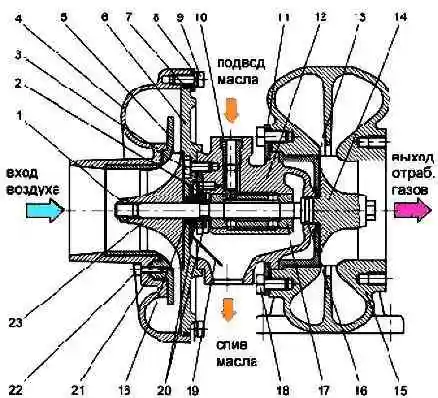
Turbocharger: 1 - compressor wheel nut; 2 - thrust bearing; 3 - bolt; 4 - compressor housing; 5 - insert; 6 - cover of the compressor housing; 7 - sealing ring; 8 - compressor plate; 9 - bolt; 10 - bolt-stopper; 11 - turbine plate; 12 - bearing housing; 13 - turbine housing spacer; 14 - turbine wheel with a shaft; 15 - turbine housing; 16 - sealing rings; 17 - bushing; 18 - bolt; 19 - oil drop screen; 20 - thrust washers; 21 - sealing ring; 22 - screw; 23 - compressor wheel
The turbocharger (fig. 1) consists of a single-stage centrifugal compressor and a radial centripetal turbine.
The turbine wheel 14 and the compressor wheel 23 are located at opposite ends of the rotor shaft cantilevered with respect to the bearing sleeve 17.
The impeller 23 of the centrifugal compressor is a semi-open type, with blades bent against rotation, cast from an aluminum alloy.
It is pressed onto the shaft and secured with nut 1, installed with sealant.
Turbine impeller 14 is a semi-open type, with radial blades, made by casting from a heat-resistant alloy. It is connected to the shaft by friction welding.
The turbine housing is made of heat-resistant cast iron. Gas is supplied to the turbine wheel by two narrowing channels.
At the end of the turbine housing there are studs for fastening the exhaust pipeline.
Compressor housing 4, bearing housing insert and cover 6 are made of aluminum alloy.
The bearing housing cover 6 is attached to the bearing housing with bolts 3 using sealant.
The turbocharger uses plain bearing 17 in the form of a sleeve made of aluminum alloy.
It is installed in the bore of the cast-iron bearing housing 12 and is kept from axial movements by a stopper bolt 10.
Lubrication of the turbocharger bushing is carried out under pressure from the engine lubrication system.
The carefully balanced rotor is mounted in hub 17.
Axial forces acting on the rotor are perceived by the thrust bearing 2. Split sealing rings 16 made of special cast iron are installed at each end of the rotor shaft.
The turbocharger is attached to the exhaust manifolds by the turbine housing.
The outlet of the compressor housing is connected through the pipes and the aftercooler to the intake manifolds of the engine.
Turbocharger maintenance
Maintenance of the turbocharger should be carried out every 3000 hours of engine operation.
During maintenance, check the axial and radial play of the rotor using an indicator.
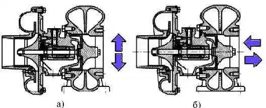
The backlash is defined as the difference between the indicator readings when the shaft deviates in two mutually opposite directions (Fig. 2).
Permissible limiting backlash values axial - 0.20 mm, radial - 0.80 mm. If the backlash is greater than the limit values, the turbocharger must be replaced.
Remove deposits from the compressor turbine housing and impellers once a year.
Compressor parts should be cleaned with gasoline, turbine parts - with a calciner.
When installing the turbocharger on the engine, carefully monitor the cleanliness of the pipelines connected to the turbocharger and the absence of objects and debris in them.
After installing the turbocharger, fill the bearing housing with clean oil through the oil inlet.
Carefully monitor the absence of leaks and leaks in air, gas, oil pipelines and their connections.
It should be borne in mind that the optimum operation of the turbocharger is carried out in the range of a higher engine speed.
Turbocharger disassembly and assembly
To clean the parts of the turbocharger, perform its partial disassembly, for this:
- 1. Remove the turbocharger from the engine.
- 2. Put marks on the turbocharger housings in such a way as to maintain the relative position of the housings during assembly.
- 3. Loosen the compressor housing bolts and remove the housing, being careful not to skew it, so that Be careful not to damage the compressor wheel blades.
- 4. Unscrew the bolts securing the turbine housing and remove the housing. If it is difficult to unscrew the bolts, lubricate their threads with diesel fuel.
Further disassembly of the turbocharger under operating conditions is not allowed.
Assemble the turbocharger in the reverse order of disassembly. Install the housings carefully, protecting the blades of the impellers from damage.
To ensure the correct relative position of the cases, use the marks made before disassembly.
We also look at the article - Repair of the turbocharger of a MAZ car
Air filter maintenance
Untimely maintenance of the air filter impairs air purification and leads to the penetration of dust into the engine, which causes increased wear of the cylinder-piston group and premature engine failure.
Proper operation of the engine requires regular maintenance of the air filter, as well as constant attention to the condition of its parts, especially seals, and to the correct installation of the air filter.
Maintenance of the first stage of the air filter should be carried out periodically during seasonal maintenance.
When working for a long time in conditions of increased dustiness and with sudden changes in environmental conditions, the terms of service should be determined based on experience in these conditions and the state of the first stage.
To service the first stage of the filter, unscrew the nuts securing the hopper. Remove the hopper, hopper cap and remove dust from it.
Unscrew the nut securing the filter elements and remove them.
Wash the air filter housing in gasoline, diesel fuel or hot water, dry it.
Pay attention when assembling the air filter:
- on the condition of the gaskets. Replace torn gaskets. The quality of the seal is controlled by the presence of a continuous imprint on the gasket.
- When using two filter elements, a spacer between them is required.
- The arrow on the hopper should be pointing up.
The filter element should be serviced according to the indication of the air filter clogging indicator: in the absence of an indicator - at TO-2, and in conditions of increased dustiness - more often, based on operating experience in these conditions.
The estimated service life of the filter element is 1500 hours.
Excessively frequent maintenance of the filter element reduces its service life, since the total number of element maintenance is limited (no more than 6 times) due to possible destruction of the filter cardboard.
To service the element, remove the hopper, unscrew the fastening nut and remove the element from the filter housing.
If there is soot-free dust on the cardboard element or if it is to be used immediately, blow the element with dry compressed air until the dust is completely removed.
To prevent the filter paper from bursting, the compressed air pressure should not exceed 300 kPa (3 kgf/cm 2).
The jet of air should be directed at an angle to the surface and adjust the force of the jet by changing the distance of the hose from the element.
If there is dust, soot, oil on the cardboard, if blowing with compressed air is ineffective, wash the element in a solution of detergent OP-7 or OP-10 (GOST 8433-81) in warm (40-50 ° C) water with a concentration of 20 -25 g of substance per 1 liter of water.
Instead of a solution of OP-7 or OP-10, you can use a solution of the same concentration of household washing powders.
To wash the element, immerse it for half an hour in the indicated solution, followed by intensive rotation or dipping in the solution for 10-15 minutes.
After rinsing in the solution, rinse the element in clean warm water and dry thoroughly.
For drying, it is forbidden to use an open flame and air with a temperature above 70 ° C.
After each maintenance of the element or when installing a new one, check its condition visually by illuminating it from the inside with a lamp.
In the presence of mechanical damage, rupture of corrugated cardboard, peeling of covers and cardboard from glue, which can lead to dust leakage, replace the element.
New filter element 8421.1109080, 238Н-1109080 must contain:
- 215-220 corrugations with a corrugation width of 55 mm;
- 235-245 corrugations with a corrugation width of 48-50 mm.
Checking the tightness of the intake tract
The tightness of the intake tract must be ensured by the sealing and fasteners of the intermediate pipelines.
Pay close attention to the condition and correct installation of the sealing and fasteners of the system: sleeve in, gaskets, clamps.
If necessary, replace.
In the absence of tightness, dust and dirt will inevitably get into the engine cylinders along with air, which will lead to premature wear of the parts of the cylinder-piston group.
Check the tightness of the intake tract by creating excess pressure in the tract with the addition of smoke.
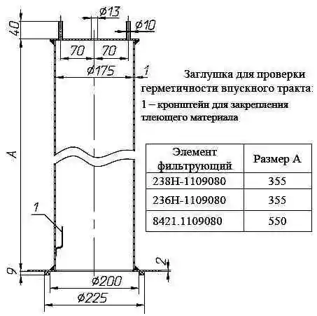
To check the tightness of the intake tract, instead of the filter element, install a plug (see Fig. 3) with smoldering material fixed inside it (tow, industrial cotton, etc.).
The size of the plug depends on the size of the air filter element, in place of which the plug is installed.
Connect a compressed air source to one of the tubes Ø10x1 of the plug, and a control tube with a tap or clamp to the other.
You can use a tire inflation pump or an industrial network with an air pressure of 10-20 kPa (0.1-0.2 kgf / cm 2) as a source of compressed air; higher pressure will destroy the pipelines.
Temporarily opening the control tube, make sure that the intake tract is filled with smoke, then supply air into the tract for 2-3 minutes, checking the condition of the intake tract by external inspection.
Smoke will be observed in places of leaks.