The car has two round headlights. Headlight bulbs – double-filament (H4)
The voltage on the lamp filaments is supplied through the low and high beam relay type 113.3747, located under the instrument panel on the left side.
Relay characteristics: switching voltage at temperature (20±5)°С – no more than 8 V, winding resistance – (85±8.5) Ohm.
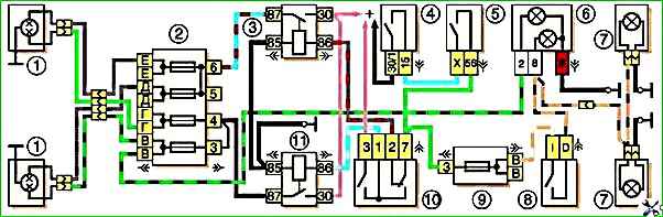
Scheme for switching on headlights and fog lights: 1 - headlights; 2 - main fuse block; 3 - relay for turning on low beam headlights; 4 - ignition switch; 5 - external lighting switch; 6 - control lamps for high beam headlights (left) and fog lights (right); 7 - fog lamps in the rear lights; 8 - fog light switch; 9 - additional fuse block; 10 - headlight switch; 11 - relay for high beam headlights
Voltage is supplied to the relay windings if the exterior lighting switch key is fully pressed (then the choice between low and high beam is dependent on the position of the steering column headlight switch) or regardless of the switch position - if the driver pulls the left steering column switch towards himself (turns on high beam headlights).
Some cars can be equipped with a hydraulic headlight corrector, designed to change the angle of the headlights depending on the vehicle load.
Removing and disassembling the headlight, replacing the lamp
Disconnect the negative cable from the battery.
Remove the radiator trim.

Use a Phillips screwdriver to loosen the three screws securing the rim of the optical element to the headlight housing.

Turn the bezel counterclockwise and remove it.

Take out the optical element of the headlight and disconnect the block from the lamp.

Opening the two ears of the wire holder, remove the lamp.

We take the lamp, suitable for use or new, only by the base, without touching the glass bulb

To remove the headlight housing in the engine compartment, disconnect the headlight wire block

Pry up the rubber plug of the mudguard with a screwdriver, take it out and push the block into the resulting hole.
Disconnect the hydraulic corrector from the headlight

Use a Phillips screwdriver to unscrew the four screws securing the headlight housing to the body.

Remove the headlight housing. After installing the headlight on the car in the reverse order, we adjust it
Adjusting the headlights
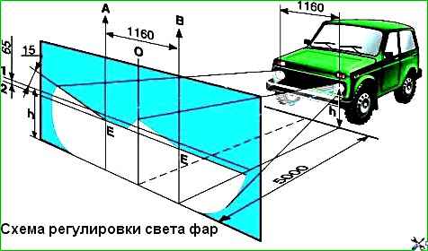
Choose a flat horizontal area within the base of the car at a distance of 5 m from the screen - a light wall of a building, garage, etc.
You can use a sheet of plywood or hardboard measuring 1x2 m.
Gas up the car, put the tools and spare wheel in their original places, check the tire pressure on all wheels.
In the dark, place the car on the selected site perpendicular to the screen, the distance between the headlights and the screen should be 5 m.
Place an assistant in the driver's seat or place a 75 kgf load and slightly rock the car from the side to install the suspensions.
Measure the distance from the centers of the headlights to the floor, at this height draw a line on the screen, and 120 mm below it - a second one (if a headlight range control is installed, the second line is drawn 65 mm below the first).
Draw a vertical center line on the screen (the distances from it to the centers of the left and right headlights should be equal) and lines corresponding to the centers of the headlights.
Set the headlight range adjustment control (if equipped) to the minimum load position.
Cover one of the headlights with a piece of cardboard, plywood, etc.
Turn on low beam headlights.
Opposite the recesses in the rim of the optical element and the radiator grille there are headlight adjustment screws.
Use the adjusting screws to ensure that the upper boundary of the light spot (horizontal) coincides with the bottom line, and the point where the beam breaks (the point of intersection of the horizontal and inclined sections) coincides with the vertical line of the center of the headlight.
To adjust the headlight beam in the vertical plane, screws “C” and “D” are turned in the same direction and at the same number of turns.
The difference in revolutions of one screw without correction of the other should not exceed 3 revolutions.
In the horizontal plane, the headlights are also adjusted with screws “C” and “D”, but by rotating them in different directions.
For example, if one screw is turned one turn clockwise, then the second screw must be turned one turn counterclockwise.
Adjust the second headlight by closing the first one.

Use a Phillips screwdriver to turn the outer screw C for adjusting the light beam of the right headlight

Use a Phillips screwdriver to turn the internal screw D for adjusting the light beam of the right headlight
Removing the headlight hydraulic corrector
We disconnect the hydraulic corrector from the headlights and instrument panel when removing these components. We completely dismantle it for replacement.


To disconnect the hydraulic corrector working cylinder from the headlight, press the latch, turn it counterclockwise and remove the hydraulic corrector working cylinder from the headlight.

Having removed the rubber plug from the mudguard, we remove the working cylinder into the engine compartment.
We similarly remove and remove the working cylinder of the other headlight.

To remove the main cylinder of the hydraulic corrector in the cabin, pull it towards you and remove the control handle

Use a 21mm socket to unscrew the nut securing the master cylinder to the instrument panel

We remove the main cylinder of the hydraulic corrector from under the instrument panel
Having removed the plug from the front panel, we bring both working cylinders into the passenger compartment through the resulting hole.
Install the headlight hydraulic corrector in the reverse order.