The wires in these diagrams have a letter color designation and a designation of the number of the circuit element to which this wire is connected
The number of the connector contact is indicated through a slash.
The symbol “S 1/29” means that the wire is connected to contact 29 of the circuit element under number 1 through a connection point not shown in the diagram.
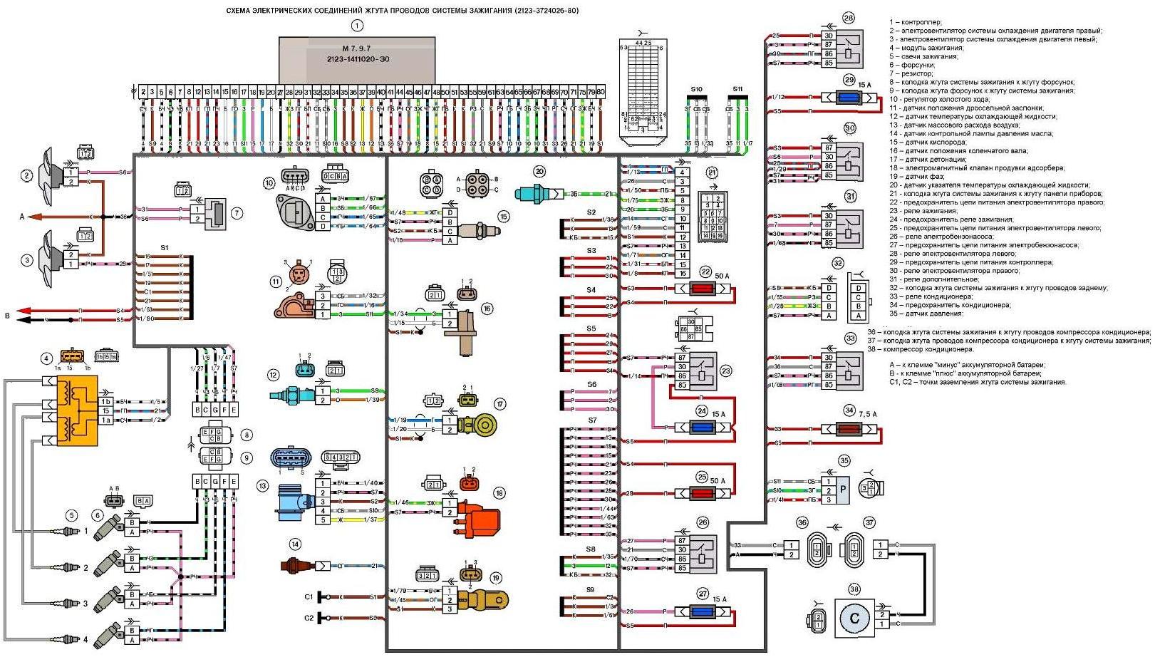
Wiring harness diagram of the ignition system: 1 - controller; 2 - right electric fan of the engine cooling system; 3 - left electric fan of the engine cooling system; 4 - ignition module; 5 - spark plugs; 6 - injectors, 7 - resistor; 8 - connector of the ignition system harness to the injector harness; 9 - connector of the injector harness to the ignition system harness; 10 - idle speed control; 11 - throttle position sensor; 12 - coolant temperature sensor, 13 - mass air flow sensor; 14 - oil pressure warning lamp sensor; 15 - oxygen sensor; 16 - crankshaft position sensor; 17 - knock sensor; 18 - electromagnetic valve of the adsorber purge; 19 - phase sensor; 20 - coolant temperature gauge sensor, 21 - connector of the ignition system harness to the instrument panel harness; 22 - fuse of the power supply circuit of the right electric fan; 23 - ignition relay, 24 - fuse of the ignition relay; 25 - fuse of the power supply circuit of the left electric fan; 26 - relay of the electric fuel pump 27 - fuse of the power supply circuit of the electric fuel pump; 28 - relay of the left electric fan; 29 - fuse of the power supply circuit of the controller; 30 - relay of the right electric fan; 31 - additional relay; 32 - connector of the ignition system harness to the rear wiring harness; 33 - air conditioner relay; 34 - fuse of the air conditioner; 35 - pressure sensor; 36 - connector of ignition system harness to air conditioning compressor wire harness; 37 - connector of air conditioning compressor wire harness to ignition system harness; 38 - air conditioning compressor; A - to the negative terminal of the storage battery; B - to the positive terminal of the storage battery; C1, C2 - grounding points of ignition system harness.
1. Ignition System Wiring Harness Wiring Diagram
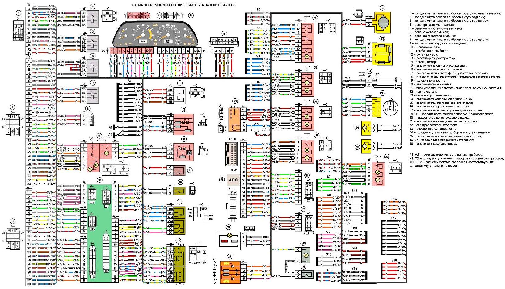
Instrument Panel Wiring Harness Wiring Diagram: 1 - Instrument Panel Harness Connector to Ignition System Harness; 2 - Instrument Panel Harness Connector to Rear Harness; 3 - Instrument Panel Harness Connector to Front Harness; 4 - Fog Light Relay; 5 - Power Window Relay; 6 - Horn Relay; 7 - seat heater relay; 8 - instrument panel harness connector to front harness; 9 - exterior lighting switch; 10 - mounting block, 11 - instrument cluster, 12 - starter relay, 13 - headlight range control regulator; 14 - potentiometer, 15 - brake light switch; 16 - horn switch, 17 - headlight and turn signal switch; 18 - windshield wiper and washer switch, 19 - diagnostic connector; 20 - ignition switch, 21 - vehicle anti-theft alarm system control unit; 22 - cigarette lighter; 23 - indicator lamp unit; 24 - hazard warning switch, 25 - rear window heating switch; 26 - fog light switch, 27 - rear fog light switch; 28, 29 - instrument panel harness connectors to the radio, 30 - glove compartment light, 31 - glove compartment light switch; 32 - heater motor; 33 - additional resistor; 34 - instrument panel harness connectors and light harness; 35 - heater motor switch; 36, 37 - heater lever light panel; 38 - air conditioner switch; A1, A2 - instrument panel harness grounding points X1, X2 - instrument panel harness connectors to the instrument cluster; Ш1, Ш5 - connectors of the mounting block to the corresponding instrument panel harness connectors
2. Wiring diagram for instrument cluster harness
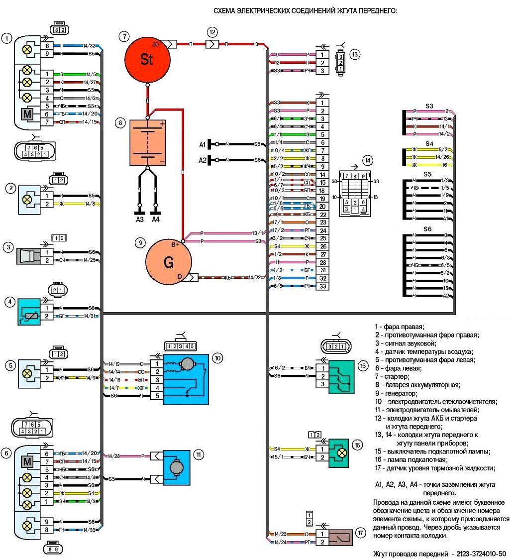
Wiring diagram for underhood harness: 1 - right headlight 2 - right fog lamp; 3 - horn; 4 - air temperature sensor; 5 - left fog lamp; 6 - left headlight; 7 - starter; 8 - battery; 9 - generator; 10 - windshield wiper motor; 11 - washer motor; 12 - battery and starter harness and front harness pads; 13, 14 front harness to instrument panel harness pads; 15 - underhood lamp switch; 16 - underhood lamp; 17 - brake fluid level sensor; A1, A 2, A 3, A 4 - front harness grounding points. The wires in this diagram have a letter color designation and a designation of the number of the circuit element to which this wire is connected. The contact number of the pad is indicated after a slash. Front wiring harness 2123-3724010-50
3. Wiring diagram of the underhood harness:
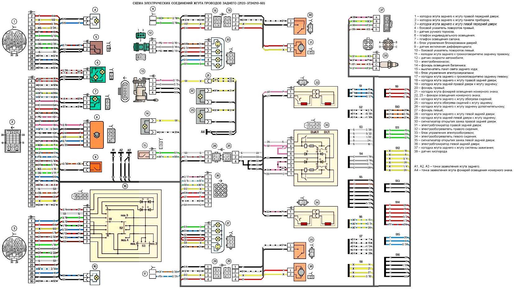
Wiring diagram of the rear harness: 1 - connector of the rear harness to the harness of the right front door 2 - connector of the rear harness to the harness of the instrument panel, 3 - connector of the rear harness to the harness of the left front door, 4 - right side turn signal, 5 - handbrake sensor, 6 - individual lighting lamp, 7 - interior light, 8 - door lock control unit, 9 - differential engagement sensor; 10 - left side turn signal; 11 - rear harness connectors to rear right loudspeaker; 12 - vehicle speed sensor: 13 - electric fuel pump 14 - trunk light; 15 - reversing light switch; 16 - electric mirror control unit; 17 - rear harness connectors to rear left loudspeaker; 18 - rear harness connector to rear right door harness; 19 - rear right door harness connector and rear harness: 20 - right light, 21 - license plate light harness connector, 22, 23 license plate lights; 24 - connector rear harness to seat heating harness, 25 - connector seat heating harness to rear harness. 26 - connector rear harness to rear additional harness; 27 - left lamp; 28 - connector rear harness to left rear door harness; 29 - connector rear left door harness and rear harness: 30 - right rear door lock open indicator, 31 - right rear door electric lock, 32 - right seat heater, 33 - electric heating control unit; 34 - left seat heater, 36 - left rear door electric lock, 35 - left rear door lock open indicator. 37 - connector rear harness to ignition system harness, 38 - oxygen sensor. A1, A 2, A 3 - rear harness grounding points; A 4 - License Plate Light Harness Grounding Point
4. Rear Vehicle Harness Wiring Diagram:
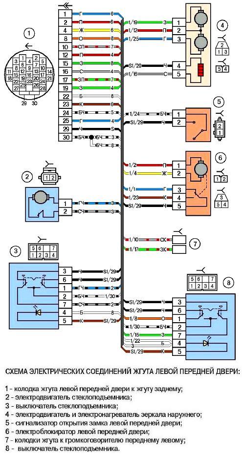
Left Front Door Harness Wiring Diagram: 1 - Left Front Door Harness Connector to Rear Harness; 2 - Window Lift Motor; 3 - Window Lift Switch; 4 - Outside Mirror Motor and Heater; 5 - left front door lock opening indicator; 6 - left front door electric lock; 7 - wiring harness connectors to the front left speaker; 8 - window lift switch.
5. Left front door wiring harness electrical connection diagram:
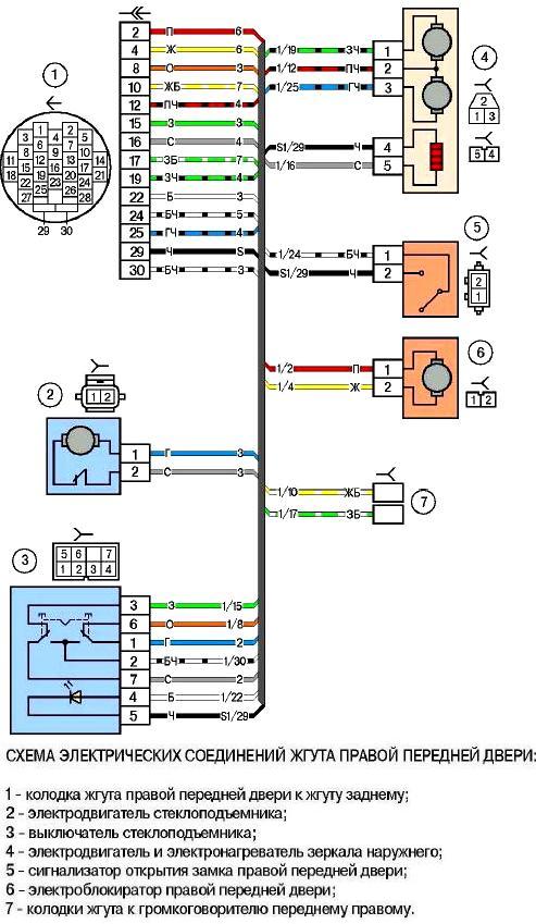
Right door wiring harness electrical connection diagram: 1 - right front door wiring harness connector to the rear wiring harness; 2 - window lift motor; 3 - window lift switch; 4 - outside mirror motor and heater; 5 - right front door lock open indicator; 6 - right front door electric lock; 7 - front right speaker harness connectors
6. Right door harness electrical connection diagram
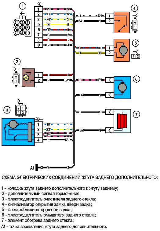
Electrical wiring diagram electrical connections of the rear auxiliary harness: 1 - connector of the rear auxiliary harness to the rear harness; 2 - additional brake light; 3 - rear window wiper motor; 4 - tailgate lock open indicator; 5 - tailgate electric lock; 6 - rear window washer motor; 7 - rear window heating element; A1 grounding point of the rear auxiliary harness
7. Electrical connections diagram of the rear auxiliary harness
")

")
")
")
")
")
")
")