The control oxygen concentration sensor (lamda probe) is installed in the exhaust pipe of the exhaust system
The controller calculates the fuel injection pulse duration based on parameters such as air mass flow, crankshaft speed, coolant temperature, and throttle position.
Based on the sensor's signal about the presence of oxygen in the exhaust gases, the controller adjusts the fuel supply by the injectors so that the exhaust gas composition is optimal for the efficient operation of the catalytic converter.
The controller constantly supplies a stabilized reference voltage of 450 mV to the sensor circuit.
The oxygen contained in the exhaust gases creates a potential difference at the sensor output, varying from approximately 50 to 900 mV.
A low signal level corresponds to a lean mixture (oxygen present), and a high level of rich (oxygen absent).
When the oxygen concentration sensor is cold, there is no output signal from the sensor, since its internal resistance in this state is very high, several megohms.
In this case, the controller controls the injection system without taking into account the voltage on the sensor, the engine management system operates in an open loop.
For normal operation, the oxygen concentration sensor must have a temperature of at least 360 ° C, therefore, for rapid warm-up after starting the engine, a heating element is built into it, which is controlled by the controller.
As the sensor warms up, its resistance drops, and it begins to generate an output signal.
Then the controller turns off the heating of the sensor and begins to take into account the signal from the oxygen concentration sensor to control fuel supply in closed loop mode.
The oxygen concentration sensor can be poisoned as a result of using leaded gasoline or using sealants containing a large amount of silicone (a silicon compound with a high volatility).
Silicone vapors can enter the combustion chamber through the crankcase ventilation system.
The presence of lead or silicon compounds in the exhaust gases can cause the sensor to fail.
If the oxygen concentration sensor fails, the controller turns on the control system malfunction indicator and controls the fuel supply in an open loop.
The diagnostic oxygen concentration sensor is installed in the exhaust system after the catalytic converter.
The design and operating principle of the diagnostic sensor are the same as those of the control oxygen concentration sensor.
The signal generated by the sensor indicates the presence of oxygen in the exhaust gases after the neutralizer.
If the neutralizer is operating normally, the readings of the diagnostic sensor will differ significantly from the readings of the control sensor.
The output voltage of the warmed-up sensor when operating in closed-loop mode and in a serviceable neutralizer should be in the range from 590 to 750 mV.
If the diagnostic oxygen concentration sensor or its circuits fail, the controller stores a fault code in its memory and turns on the fault indicator in the instrument cluster.
Replacing oxygen concentration sensors
Oxygen sensors need to be replaced after 75 thousand km of the car's mileage.
Unscrew the sensors when the engine has cooled down.
Disconnect the negative terminal of the battery.
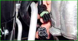
To replace control sensor, in the engine compartment we press the lock of the wiring block and disconnect it.
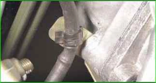
We disconnect the plastic holder of the sensor wiring harness from the bracket
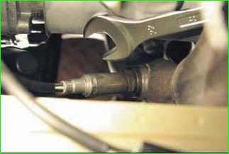
Use a 22 mm wrench to unscrew the sensor
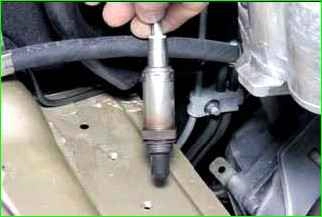
Remove the sensor from the engine compartment
If the sensor is very stuck and cannot be unscrewed with an open-end wrench, then if you are replacing the sensor, you can cut the sensor wires with side cutters and unscrew them with an open-end wrench.
You can also disassemble the wiring harness, if the sensor cannot be replaced.
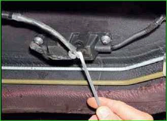
To replace the diagnostic oxygen sensor, use a screwdriver to pry the wire holder from the protective cover of the wire blocks from underneath the car.
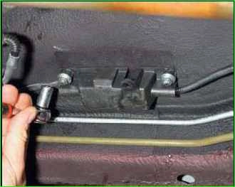
Use a 10 mm wrench to loosen the two nuts.
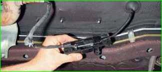
Remove the protective cover with the wire blocks
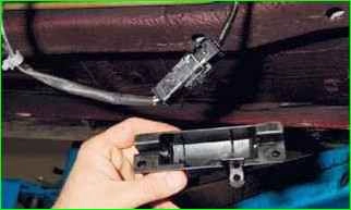
Remove the wire blocks from the protective casing
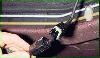
Press the block retainer, disconnect the wire harness blocks
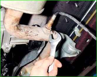
Use a 22 mm wrench to unscrew the sensor
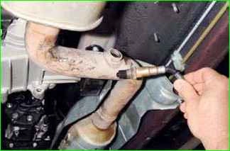
Removing the diagnostic sensor
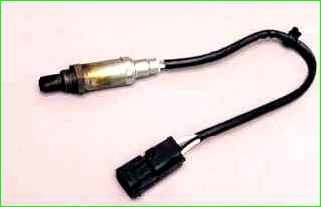
When installing the sensor, make sure that dirt and grease do not get on the pads or the sensor itself.
Install the sensors in the reverse order.


