When the ignition is turned on, the controller exchanges information with the immobilizer control unit, which is designed to prevent unauthorized engine starting.
The engine can only operate if the controller has received the correct password from the control unit.
The immobilizer control unit is mounted on a bracket under the instrument panel console screen on the left side.
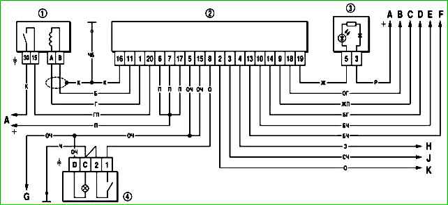
Wiring diagram of the vehicle anti-theft alarm system: 1 - ignition switch; 2 - APS control unit; 3 - control lamp unit; 4 - rear fog light switch; A - to power sources; B - to the controller, contact "55"; C - to the diagnostic connector; D to the switch in the driver's door pillar; E - to the switches in the door pillars; F - to the external lighting switch (turning on the parking lights); G - to the fog lamps in the rear lights; H - to the external lighting switch (turning on the headlights); J - to the fog light switch; K - to the electric window relay (terminal "85")
The wiring diagram of the car anti-theft system (APS) is shown in the figure.
The description of the APS operation is given in the car operating manual, diagnostics and repair - in the engine management system repair manual.
To remove the unit, disconnect the negative battery cable.

Removing the floor tunnel trim

Using a 10 mm socket, unscrew the two nuts securing the control unit

Disconnect from block connector harness

Install the unit in the reverse order
Removing and installing the remote control unit of the electrical package
In the pictures, the instrument panel is removed.
Disconnect the negative terminal of the battery.

Using a 10 mm wrench, unscrew the two nuts securing the unit and remove the unit

Pressing the latch, disconnect the wiring block from block

The unit marking is on its body
We install the control unit in the reverse order