We perform the work when replacing the gearbox or when the control drive parts of the mechanism are faulty
We install the car on an inspection pit or lift
We remove the intermediate shaft (see the article - Replacement and repair of the intermediate shaft Niva Chevrolet)
We remove the floor tunnel lining (see the article - Removing the floor tunnel lining Niva Chevrolet)

In the car, unscrew the handle gear shift lever

Removing the handle together with the cover

Removing the protective cover from the gear shift lever

Remove the sealing boot

Using a 17 key, unscrew the nut securing the gear selector control drive to the rear support
Under the nut spring and flat washers and spacer sleeve are installed.
After unscrewing the nuts securing the rear support of the power unit, lower the rear end of the gearbox (see the article - Replacing the supports of the power unit of the VAZ-2123 car)

Using a 13 mm open-end wrench, loosen the tie rod end clamp bolt
Using a screwdriver, loosen the clamp

Using a 13 mm head with an extension, unscrew the three bolts securing the gear selector control drive bracket to the rear cover of the gearbox

Removing the tip from the hole in the drive rod, remove the gear selector control drive assembly

To remove the rear drive support, use a 10 mm head to unscrew the four nuts securing the support to the body

After removing the support from the studs, use a screwdriver squeeze the wire holder petals and disconnect the holder from the support

Remove the rear support of the gear selection mechanism control drive
Install the drive in the reverse order.
Move the gearbox control drive rod to neutral position.
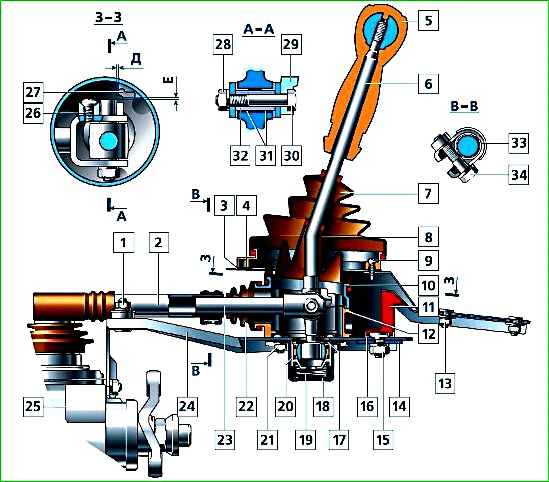
Gear shift control drive: 1 - nut a support plate fastening; 2 - gearbox control rod; 3 - hatch cover gasket; 4 - gearshift lever hatch cover; 5 - gearshift lever handle; 6 - gearshift lever; 7 - gearshift lever boot; 8 - sealing boot; 9 - hatch cover fastening screw; 10 - gearshift lever upper housing; 11 - rear support; 12 - gearshift lever lower housing; 13 - rear support fastening nut; 14 - rear support washer; 15 - nut; 16 - spacer ring; 17 - retaining ring; 18 - ball joint housing; 19 - gearshift lever spring; 20 - ball joint slider; 21 - ball joint housing fastening nut; 22 - protective boot; 23 - rod end; 24 - support plate; 25 - gearbox; 26 - locking stop fastening screw; 27 - reverse gear locking lining; 28 - tie rod end fastening bolt nut; 29 - locking stop; 30 - tie rod end fastening bolt; 31 - bushing; 32 - spacer bushing; 33 - control drive tie rod clamp; 34 - clamp bolt
When installing the drive, hold the gearshift lever in the position determined by the following dimensions in millimeters:
Д = 1.5±0.5;
Е = 1±0.5 (see Figure 12).
In this position of the lever, tighten the clamp bolt of the control drive rod to a torque of 24.5 Nm
Disassembling the gear control drive
Remove the control drive as described above

Using a 13 key, unscrew the two nuts securing the bracket to the support plate

Remove the bracket

Remove the rubber dampers from the bracket studs
Change the dampers if necessary

Remove the protective rubber cover from the tie rod end

Using a 10 mm wrench, unscrew the four bolts securing the gear shift lever housings

Remove the upper metal housing of the lever

Removing the lower plastic housing of the lever

Removing the lower housing sealing gasket

Using a 13 mm wrench, unscrew the nut of the bolt securing the end of the tie rod to the gear shift lever

Remove the bolt

Removing we have the end of the tie rod

We take out the metal spacer sleeve from the lever

We pry it out with a screwdriver two plastic bushings from the lever hole
Change the bushings if necessary

Using a 10 mm wrench, unscrew the three nuts securing the ball joint housing

Removing the housing

Removing the lever spring

Removing sealing gasket

Remove the gear shift lever assembly with the slider from the support plate

With a lock puller rings, compress the retaining ring and remove it

Removing the gear shift lever ball joint slider

Remove the lower sealing ring from the lever support

Use a screwdriver to pry off the upper sealing ring

Remove the support from the gear shift lever

Using a 10 key, unscrew the two bolts securing the reverse gear lock pad to the upper housing of the gear shift lever

Remove the cover

Using a Phillips screwdriver, unscrew the screw securing the locking stop to the tie rod end fork

Remove the locking stop
Assemble the gear selection mechanism control drive in the reverse order.
Apply a thin layer of Litol-24 plastic grease to the slider and ball joint housing
Disassembling and assembling the gear selection mechanism
Remove the gear selection mechanism, for this:
Set the gear selection lever to neutral position

Using a 10 key, unscrew the three nuts securing the gear selection mechanism housing

Remove the gear selection mechanism assembly

Remove the sealing gasket

Use a marker to mark the relative positions of the guide plate, washers and the mechanism housing

Using a 10 key, unscrew the nut of the bolt securing the guide plate and washers to the housing, holding the bolt head with a 10 key
Also unscrew two more bolts

Remove the lower washer of the guide plates

Having removed one guide plate with two springs
Remove the guide plate from the lower end of the lever

Remove the upper washer of the guide plate

Use a screwdriver or tweezers to remove the rubber sealing rings of the bolts from the grooves in the housing

Removing the gear selector lever housing

Removing the lower gasket of the ball joint housing

We move the cover from the fork of the gearbox control drive rod

Having supported the flange of the ball joint on the jaws of the vice, with a sharp downward movement we move the drive rod and the housing of the rod hinge from the tail of the gear selection lever, overcoming the resistance of the support ring.

Removing the pressure plate

Removing the flange

Remove the upper housing gasket

Pry off the retaining ring with a screwdriver

Removing the sealing ring

Removing the spherical support washer

Disconnecting the lever and the ball joint housing

Removing the spring from the drive rod hinge housing

Removing the protective cover of the housing

Removing the hinge axis from the holes in the drive rod fork

Removing the housing

Plastic bushings are installed in the holes of the drive rod fork

To replace the drive rod clamp, unscrew the tie bolt and slide the clamp off the rod

When installing the clamp on the rod, its must be oriented so that the clamp bolt passes through the chamfer (1) on the rod. In this case, the pin (2) of the clamp will enter the slot (3) of the rod.
Move the rod cover
Assemble the gear selection mechanism in reverse order.