Anti-lock braking system is installed on the vehicle in an optional design
Anti-lock braking system is part of the vehicle's service braking system and is designed to automatically regulate the degree of wheel slippage in the direction of their rotation during braking by changing the brake fluid pressure in the working brake cylinders in order to prevent loss of control and stability of the vehicle and improve braking efficiency.
ABS also performs the functions of distributing braking forces along the vehicle's axles and distributing braking forces along the vehicle's sides when braking in a turn.
ABS consists of the following main components:

- - hydraulic unit;
- - two front wheel speed sensors;
- - two rear wheel speed sensors;
- - two front wheel rotors. The front wheel rotor is part of the outer joint;
- - two rear wheel rotors. The rear wheel rotor is part of the axle shaft;
The hydraulic unit structurally consists of an electronic control unit and a hydraulic modulator containing electromagnetic valves, a return pump and an electric motor for the return pump.
The wheel speed sensors generate signals about the speed of each wheel of the vehicle, which are transmitted to the electronic control unit of the hydraulic unit.
The operation of the wheel sensors is based on the principle of electromagnetic induction.
When the wheel rotates, the teeth and cavities of a special rotor pass by the sensor and induce an electric signal in the sensor winding, the frequency of which is proportional to the angular velocity of the wheel and the number of teeth on the rotor.
The electronic control unit logically processes the signals about the speed of the wheels and, depending on their state (excessive acceleration or deceleration of the wheel), sends control commands to the hydraulic modulator.
Based on the commands received, the hydraulic modulator turns on or off the electromagnetic valves, reduces, increases or maintains constant brake fluid pressure in the wheel brake cylinders, thereby ensuring optimal regulation of braking forces.
When the pressure decreases, excess brake fluid is pumped by the return pump to the master brake cylinder.

The basic diagram of the ABS is shown in the figure
Assignment of the hydraulic unit connector contacts:
Contact - Circuit
- 1 - Terminal "+" of the battery. Supply voltage of the hydraulic unit EBP.
- 3 - Output to the diagnostic lamp of the electronic brake force distribution.
- 4 - Input signal of the front right DSC.
- 6 - Output/input K-line.
- 8 - Input signal of the front left DSC.
- 13 - "Ground". Common power supply wire of the hydraulic unit ESP.
- 16 - Power supply voltage of the front right DSC.
- 17 - Power supply voltage of the rear right DSC.
- 18 - Input signal of the rear left DSC.
- 19 - Power supply voltage of the front left DSC.
- 25 - Terminal "+" of the battery. Power supply voltage of the hydraulic unit EMC.
- 27 - Output to the diagnostic lamp of the anti-lock braking system.
- 28 - Terminals "15" of the ignition switch. Power supply voltage of the GA ECU.
- 29 - Input signal of the rear right DSC.
- 30 - Input from the brake light switch.
- 31 - Power supply voltage of the rear left DSC.
- 38 - "Ground". Common power supply wire for the EMC and the hydraulic unit ECU.
ABS Diagnostics
The anti-lock braking system (ABS) indicator lamp lights up briefly in yellow when the ignition is turned on.
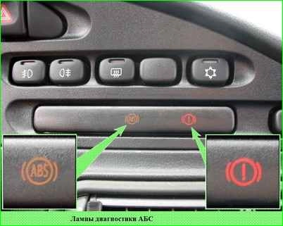
This indicates that the self-test has been completed and the indicator lamp is operational.
In cases where:
- the lamp does not light up when the ignition is turned on, lights up and does not go out, lights up while driving, there may be a malfunction in the system.
If the ABS lamp lights up, with the exception of self-testing when the ignition is turned on, it indicates that the system is not working properly sti ABS.
In this case, the operation of the hydraulic brake drive is not disrupted, but the brakes in the car will work as if the car did not have ABS.
The electronic brake force distribution indicator lamp lights up red for a short time when the ignition is turned on, simultaneously with the ABS lamp.
This indicates that the system is self-testing and the indicator lamp is working.
In cases where:
- the lamp does not light up when the ignition is turned on, lights up and does not go out, lights up while driving, there may be faults in the system.
The electronic brake force distribution lamp always lights up simultaneously with the ABS indicator lamp.
Simultaneous lighting of the ABS lamp and the electronic brake force distribution lamp, with the exception of the self-test when the ignition is turned on, indicates a failure of all ABS functions.
For To view fault codes and ABS parameters, use the DST-2, 10,12 diagnostic tool with the appropriate firmware.
List of ABS fault codes displayed by the diagnostic tool:
Code - Code description
- C0035 - Front left wheel speed sensor fault
- C0040 - Front right wheel speed sensor fault
- C0045 - Rear left wheel speed sensor fault
- C0050 - Rear right wheel speed sensor fault
- C0060 - Front left wheel inlet valve circuit fault
- C0065 - Front left wheel outlet valve circuit fault
- C0070 - Front left wheel inlet valve circuit fault right wheel
- C0075 - Front right wheel exhaust valve circuit malfunction
- C0080 - Rear left wheel inlet valve circuit malfunction
- C0085 - Rear left wheel exhaust valve circuit malfunction
- C0090 - Rear right wheel inlet valve circuit malfunction
- C0095 - Rear right wheel exhaust valve circuit malfunction
- C0110 - Hydraulic module pump motor circuit malfunction
- C0121 - Valve relay circuit malfunction
- C0161 - Brake switch circuit malfunction
- C0245 - Wheel speed sensor frequency error
- C0550 - ECU malfunction
- C0800 - Device power supply circuit malfunction
- C0640 - Incorrectly programmed information in EEPROM or defective EEPROM cell
If fault codes C0035, C0040, C0045 and C0050 are detected, check the electrical circuits to the corresponding DSC for open and short circuits, check the supply voltage of the corresponding DSC (U supply DSC ≥ 0.8 U supply ECU).
If fault code C0110 is detected, check the supply voltage at contact 1 of the harness connector to the hydraulic unit.
If fault code C0121 is detected, check the supply voltage at contact 25 of the harness connector to the hydraulic unit.
If fault code C0161 is detected, check the electrical circuit to the brake light switch for open and short circuits.
On contact 30 of the harness connector to the hydraulic unit must be:
- - low-level input voltage no more than 0.3 U power;
- - high-level input voltage no less than 0.8 U power.
If fault code C0245 is detected, check the reliability of the DSC fastening and the gaps between the DSC and the rotor.
The gap between the front wheel speed sensor and the front wheel rotor teeth must be 0.72-1.33 mm.
The gap between the rear wheel speed sensor and the rear wheel rotor teeth must be 0.13-1.12 mm.
If fault code C0800 is detected, check the supply voltage at contact 28 of the harness connector to the hydraulic unit. It should be within (10-16) V.
If fault codes C0060, C0065, C0070, C0075, C0080, C0085, C0090, C0095, C0550 are detected, replace the hydraulic unit.
The fault corresponding to code C0640 is not critical. If it occurs, further operation of the vehicle is permitted.
ABS fuse box
The ABS fuse box is located in the engine compartment on a bracket next to the battery
- 40A – Electric motor of the return pump of the ABS hydraulic unit
- 25 A – Solenoid valves of the ABS hydraulic unit
- 5A – Electronic control unit of the ABS hydraulic unit


To change the fuses, press the lock of the ABS fuse box cover

Open the cover of the box and replace the fuse
")

")
")
")
")
")
")
")