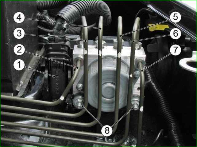
The hydraulic unit structurally consists of an electronic control unit (ECU) and a hydraulic modulator containing electromagnetic valves (EMV), a return pump and an electric motor of the return pump
Removing the ABS hydraulic unit
Preparing the car to perform the task
Disconnecting the negative terminal of the battery
Disconnect the wiring harness block from the hydraulic unit
Disconnect the brake pipes going to the brake mechanisms, the primary and secondary circuit pipes of the master brake cylinder from the ABS hydraulic module.
Install plugs in the holes of the pipes and the hydraulic unit
Loosen the two nuts 8 that secure the hydraulic unit to the bracket and remove the hydraulic unit
Installation
The hydraulic unit is supplied filled at the spare parts store.
Before installation, make sure that the hydraulic unit support damper is present and installed correctly
Install the ABS module on the bracket, aligning the grooves on the rubber bushings with the slots on the bracket, and tighten nuts 8 with a torque of 8±2 Nm.
Remove the plugs and connect the primary and secondary circuit tubes, as well as the tubes leading to the brake mechanisms, to the hydraulic unit.
Check the brake fluid level in the brake hydraulic drive reservoir, and top up to the norm if necessary.
The brake fluid level in the brake master cylinder reservoir should reach the lower edge of the filler neck with the cap installed.
Bleeding air from the brake system when installing an unfilled hydraulic unit
When installing an unfilled hydraulic unit on a vehicle, bleed the brake system using the DST-2, 10,12 diagnostic device with the appropriate firmware in the following sequence.
Connect the DST-2, 10,12 diagnostic device connector with the appropriate firmware to the vehicle diagnostic socket.
Turn on the ignition and wait for the connection to be established with the vehicle's electrical equipment.
Press the "1" button of the tester, enter the "Chassis" menu and select the ABS 9.0 diagnostic program, press the "Enter" button.
When using a device for bleeding the brakes, carry out the work in accordance with the operating instructions for the device.
If there is no device for bleeding the brakes, the air removal operation must be performed by three performers (operators).
Operator No. 1 is constantly in the passenger compartment in the driver's seat, controls the operation of the diagnostic tester, presses the brake pedal and gives commands to operator No. 2.

Operator #2 follows the instructions of operator #1 (opens and closes the bleeding nipples).
Operator #3 constantly tops up the brake fluid in the brake hydraulic drive reservoir, preventing its bottom from being exposed, in order to prevent air from entering the hydraulic drive.
Press the "4" button of the device and enter the "ABS bleeding" menu.
By pressing the "Enter" button and then the "2" button, switch to the manual bleeding mode of the brake system (the device program automatically switches to the "Phase #1" mode - rear left wheel vehicle).
Put a transparent hose on the nipple, and immerse the other end of the hose in a container partially filled with brake fluid.
Operator #1 gives the command to Operator #2 to open the nipple to bleed the brakes.
Operator #1 presses the "Enter" button of the tester and performs a series of actions consisting of pressing, holding for 1-2 seconds, and completely releasing the brake pedal during the entire bleeding phase.
At the end of the "Phase #1" bleeding mode, Operator #2, on command, tightens the nipple.
Operator #1 sharply presses the brake pedal and, holding the pedal in the pressed position, gives the command to Operator #2 to loosen the nipple.
After unscrew the nipple by 1/2 - 3/4 of a turn after 1 - 2 seconds, holding the brake pedal pressed, screw the nipple and operator No. 1 releases the pedal.
Repeat the bleeding operation until air bubbles stop coming out of the vehicle's brake system.
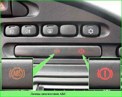
If the ABS diagnostic lamps in the control lamp unit do not light and the diagnostic device does not switch to the "Phase No. 1" mode, it is necessary to clear the ABS controller memory from accumulated errors using the diagnostic device.
While holding the brake pedal pressed, tighten the bleed nipple, release the pedal and remove the transparent hose. Wipe the nipple dry and put the protective cap on it.
WARNING. Full release of the brake pedal is necessary to send a signal about the bleeding process to the ABS controller.
The bleeding process is indicated on the display of the diagnostic tester as an increasing dark stripe at the bottom of the screen, the ABS diagnostic lamps in the control lamp block are lit at this moment.
If after the end of the bleeding phase the message "Filling not completed" appears on the tester display, it is necessary, by pressing the "Esc" and "Enter" buttons, to make a repeated attempt to bleed the corresponding circuit of the brake system, but not earlier than after 5 minutes.
During the bleeding process, do not allow the brake hydraulic reservoir to empty.
It is not allowed to use the fluid drained through the nipple to top up the brake hydraulic reservoir within 24 hours.
Press the "Up" button of the diagnostic device and switch it to the "Phase No. 2" mode bleeding the front left wheel circuit. The sequence of operations is the same as for the rear left wheel.
Press the "Up" button of the diagnostic tool and switch it to the "Phase No. 3" mode of bleeding the front right wheel circuit. The sequence of operations is the same.
Press the "Up" button of the diagnostic tool and switch it to the "Phase No. 4" mode of bleeding the rear right wheel circuit. The sequence of operations is the same.
Press the brake pedal and make sure that there is no "soft brakes" effect. Press the "Esc" button of the diagnostic device to enter the initial operating mode.
Press the tester buttons "1", "Enter", "4" in sequence to enter the "Filling Status" mode (there should be a "Done" message on the right side of the display).
Press the "Esc" button once, turn off the ignition and disconnect the diagnostic device connector from the vehicle diagnostic connector.

Check and, if necessary, bring the brake fluid level to normal in the brake hydraulic fluid reservoir.
Apply the maximum possible load to the brake pedal with your foot and check the hydraulic fluid for leaks. The brake pedal should not fall through when pressed.
Check the efficiency of the service brake by test driving or on a stand
")

")
")
")
")
")
")
")