Front door electric windows are included in some models of cars
Unlike a mechanical window lifter with a gear reducer, the electric window lifter only has a drum for the cable, driven by a gear motor
The gear motor includes a worm gear and a DC electric motor with excitation from permanent magnets.
The gear motor is reversible, the direction of rotation of its output shaft changes in accordance with the change in the direction of the current in the armature winding.
There is a built-in thermal bimetallic fuse for overload protection.

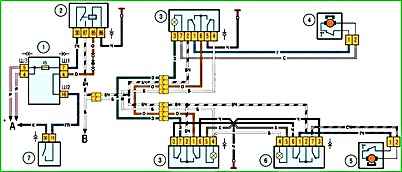
The electric window wiring diagram is shown in Fig. 1.
Gearmotors 4 and 5 are switched on by switches 3 and 6, located on the door armrests.
Power is supplied to the switches through fuse F5 only when the ignition is on, when the contacts of relay 2 are closed.
Relay 904.3747-10, located to the left of the steering column on a bracket mounted on the fuse and relay mounting block, is used to turn on the electric windows.
If the electric windows fail, remove the door trims and check if voltage is supplied to the gearmotors.
Check the fuse and relay for the window lifters on the mounting block, restore the broken wire connections, replace the faulty gearmotor.
Data for checking the gearmotor
The speed of the gearmotor shaft at idle at supply voltage (13.5 ± 0.1) V and ambient temperature (25 ± 10) °C, 56–90 min-1
Current consumption at the above load and rotation speed 1.2–5.0 A


