Put the car on a lift, turn off the ignition.
To dismantle the engine fuel system, you need to bleed the pressure in the fuel system, for this:
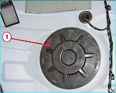
Fold the rear seat cushion forward, remove the cover 1, Figure 1, of the fuel pump hatch.
Disconnect connector 1, Figure 3-2, of the wiring harness rear from fuel pump 2.
Start the engine and let it run until it stops completely to relieve pressure in the fuel line.
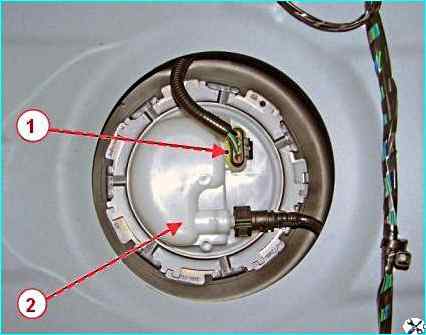
Connect connector 1, figure 2, of the rear wiring harness to fuel pump 2, install cover 1, figure 1, of the fuel pump hatch and lower the rear seat cushion.
Turn off the ignition, open the hood and disconnect the negative terminal of the wire from the battery.
Removing the vehicle's power unit
For vehicles with an air conditioning system:
Full discharge of the refrigerant from the air conditioning system in accordance with the requirements of the service equipment operating instructions.
For vehicles of all trim levels:
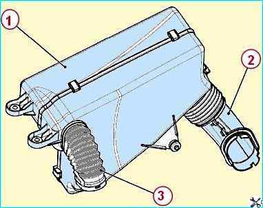
Disconnect the pipes of the resonator 1, Fig. 3, intake from the air intake and the air filter housing, use a 10 head to unscrew the two mounting bolts and remove the resonator.
Remove the intake module screen.
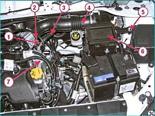
Using pliers, squeeze clamp 1, figure 4, fastenings and disconnect upper hose 3 of crankcase ventilation from cover branch pipe 7 of cylinder head.
Using a Phillips screwdriver, loosen clamp 2 fastenings and disconnect hose 4 of intake pipe from intake module.
Using 13 head, unscrew bolt 5 fastenings, disconnect air filter 6 from supports and remove air filter with hose of intake pipe in assembly.
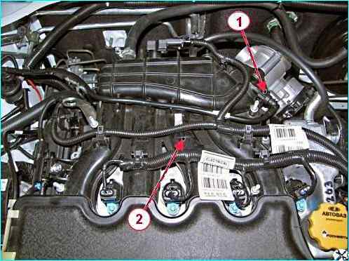
Disconnect tip 1, Figure 5, of the evaporative canister valve tube and the tube itself from intake module 2.
Disconnect the pads and connectors of the ignition system wiring harness from the connectors:
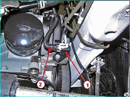
- sensor 1, figure 6, crankshaft position;
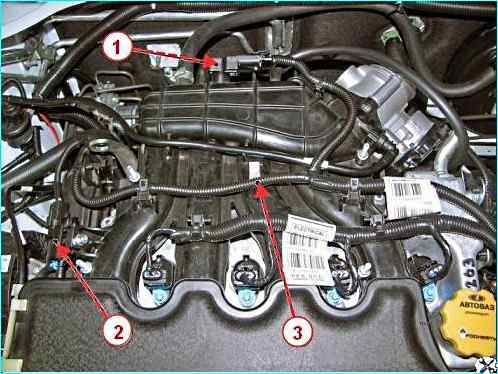
- - sensor 1, figure 7, air pressure and temperature;
- - valve 2 of the intake manifold flap (for engine 21129);
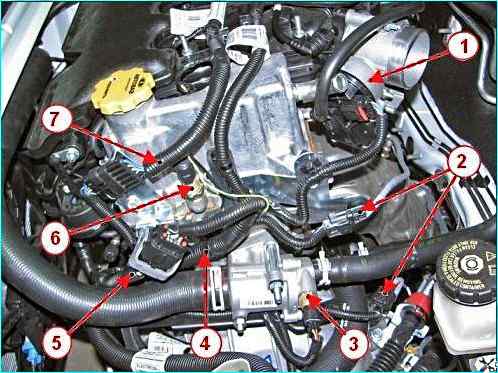
- - throttle pipe 1, figure 8;
- - oxygen content sensors 2;
- - coolant temperature sensor 3;
- - injector wire harness 5;
- - oil pressure warning lamp sensor 6;
- - ignition coil wire harness 7 (for engine 21129);
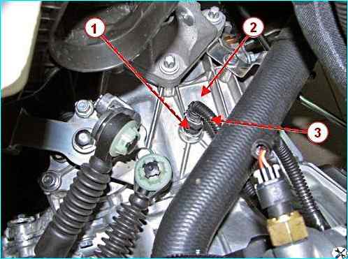
- switch 1, figure 9, reverse light on gearbox 2.
Use pliers to disconnect the clamps, cut the mounting clamps with a knife and move the ignition system wiring harness to the side.
Remove the front wheels.
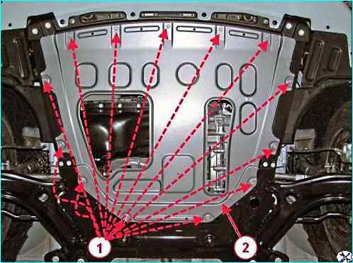
Using a 10 mm socket, unscrew the thirteen bolts 1, Figure 10, securing the engine mudguard and remove it.
For vehicles with a manual transmission:
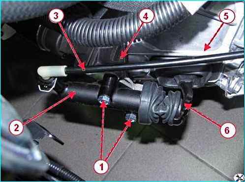
Using a 13 mm socket, unscrew the two bolts 1, Figure 11, securing the fasteners, remove the cylinder 2 of the clutch hydraulic drive without disconnecting it from the tube 3 of the hydraulic drive, and hang the cylinder on a technological hook.
For cars of all trim levels:
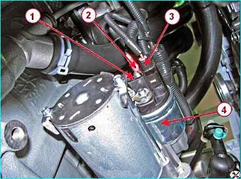
Using a 13 mm head, unscrew nut 1, Figure 12, and disconnect terminal 2 and block 3 of the wiring harness from the starter traction relay 4.
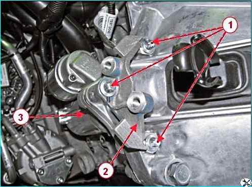
Using a Torx E10 head, unscrew the three bolts 1, Figure 13, remove the bracket 2 for fastening the clutch hydraulic cylinder (for cars with a manual transmission) and the starter 3.
Drain the coolant:
- using a 13 head, unscrew the drain plug on the cylinder block and screw in the hose nipple for draining the liquid in its place;
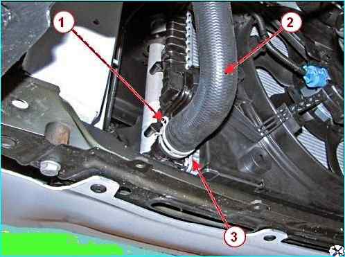
- - use pliers to loosen clamp 1, figure 14, fasteners and disconnect outlet hose 2 from radiator pipe 3;
- - unscrew the plug on the expansion tank and drain the coolant into a container;
- - install outlet hose 2 of the radiator on radiator pipe 3 and secure with clamp 1;
- - use a 13 head to unscrew the fitting and screw in the drain plug of the hole on the cylinder block.
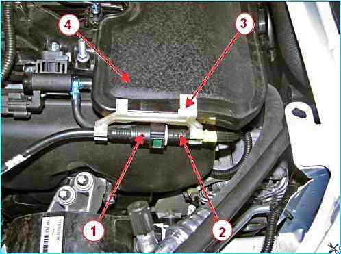
Press the clamps and disconnect the tip of tube 1, Figure 15, intermediate from tube 2 of the front fuel line and the bracket 3 for fastening the pipes on module 4 of the intake (for engine 21129).
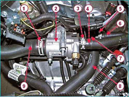
Use pliers to loosen clamp 1, Figure 16, and disconnect hose 9, radiator inlet, from thermostat 2.
Use pliers to loosen clamp 3 and disconnect hose 4, heater inlet, from thermostat.
Use pliers to loosen clamp 5 and disconnect hose 6, heater outlet, from water pump inlet pipe.
Use pliers to loosen clamp 7 and disconnect hose 8, radiator, from water pump inlet pipe.
Cut clamp securing radiator outlet hose to bracket on gearbox.
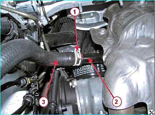
Unclamp clamp 1, figure 17, and disconnect filler hose 3 from pipe 2 supplying the water pump.
Disconnect the front wiring harness from the engine, for which it is necessary:
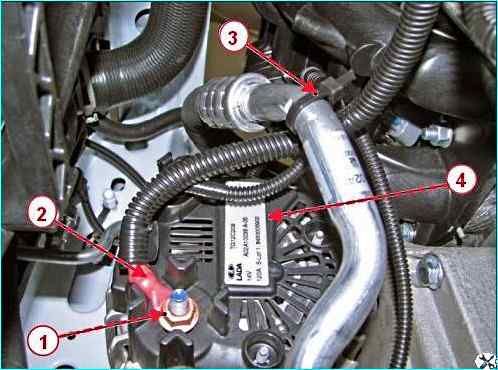
- - use a 13 mm head to unscrew nut 1, figure 18, fastenings and disconnect terminal 4 of the front wiring harness from the generator;
- - cut clamps 3 fastenings and move the front wiring harness away from the engine.
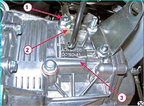
Using a 17 mm socket, unscrew nut 1, figure 19, securing terminal 2 of the ground wire from the stud on the 3rd gearbox and disconnect the terminal;
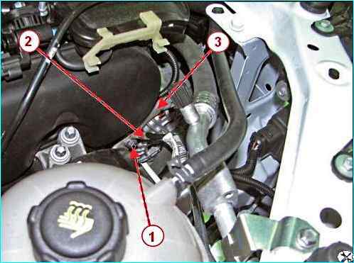
Using a 13 mm head, unscrew bolt 1, Figure 20, securing terminal 2 of the ground wire on bracket 3 of attachments and disconnect the terminal.
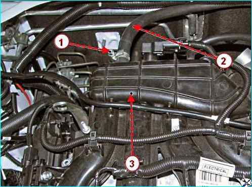
Using a Phillips screwdriver, loosen clamp 1, Fig. 21, fastening and disconnect hose 2 of the brake booster from module 3 of the intake.
For vehicles with manual transmission:
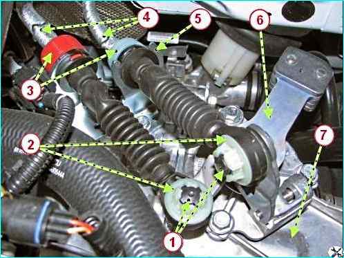
Press the clamps 1, figure 22, of the tips and disconnect the tips 2 of the gear shift cables from the levers of the gear shift mechanism 6.
Move the clamps 3 along the axis of the cables 4 in the direction from the bracket 5 and remove the cables from the slots of the bracket on the gearbox 7.
For cars with an air conditioning system:

Using an 8 mm head, unscrew the two bolts 1, Figure 23, securing the pipelines 2 to the compressor 3 of the air conditioning system and disconnect the pipelines.
Install technological plugs on the pipelines and in the compressor holes.
For cars of all configurations:
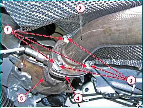
Using a screwdriver, loosen three washers 1, Figure 24, locking and with a 10 head, unscrew three nuts 3 studs securing additional muffler 2 to exhaust pipe 5 of the muffler with neutralizer assembly
Disconnect additional muffler from exhaust pipe of the muffler and remove gasket 4.
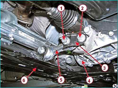
Using a 18 mm head, unscrew bolts 1 and 2, Figure 25, securing bracket 3 and rod 5 to power unit 4 and remove the bracket.
Remove the front suspension subframe 6 as an assembly.
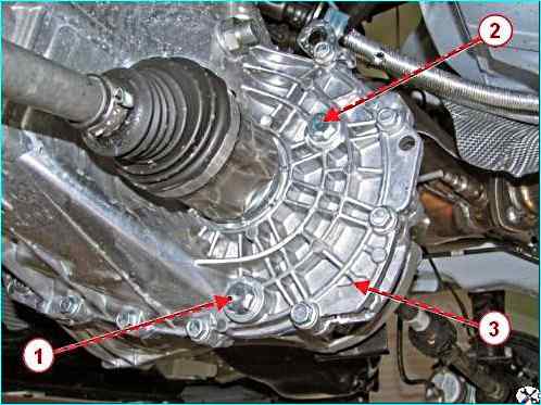
Using a 17 mm socket wrench, unscrew plug 1, Figure 26, and drain the oil from the 3rd gearbox.
Wipe the threads in the gearbox housing and on the plug, apply sealant to the threaded part of the plug.
Install plug 1, Figure 26, into the oil drain hole in the 3rd gearbox housing. Tightening torque of the plug 29 - 46 Nm (2.9 - 4.6 kgf.m).
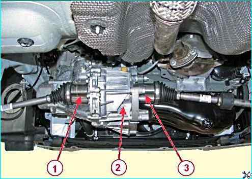
We knock out and remove the inner joints of drives 1 and 3, figure 27, of the front wheels from the gears of the semi-axles of the differential of the 2nd gearbox and install transport plugs in their place.
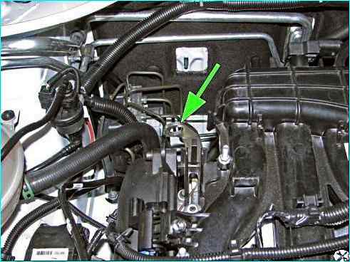
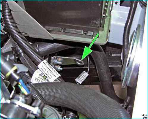
Insert the hook of the lifting clamp into the eye of the lifting eye, Figure 28 and Figure 29, of the powertrain and hang the powertrain.
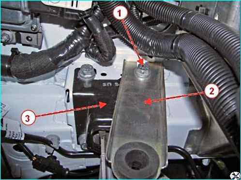
Using a 16 mm socket, loosen bolt 1, Figure 30, securing bracket 2 of the air filter and remove the bracket from the left support 3 of the power unit suspension.
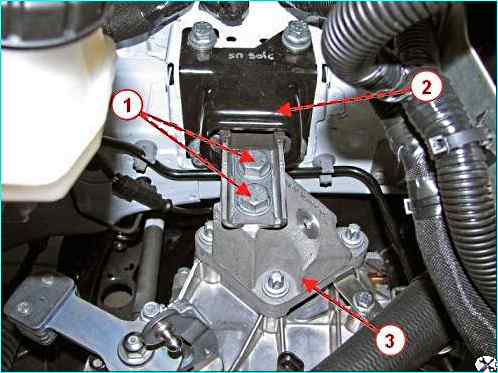
Using a 18 mm head, unscrew and remove two bolts 1, Figure 31, fastening the power unit to the left support 2 of the power unit suspension.
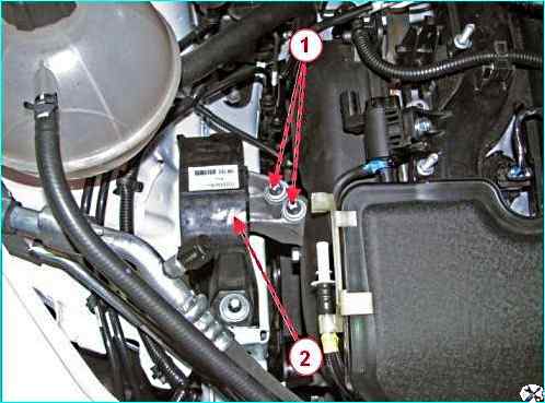
Using the Torx E12 head, unscrew and remove the two bolts 1, Figure 32, securing the power unit to the right support 2 of the power unit suspension.
Lower the power unit onto the trolley, remove the hooks of the lifting clamp from the eyes of the lifting eyes and remove the power unit from under the car.
Installing the power unit
Move the power unit on the trolley under the engine compartment of the car.
Insert the hooks of the lifting clamp into the eyes of the lifting eyes, Figures 28 and 29, of the power unit, lift the power unit and install the two bolts 1, Figure 31, fasten power unit to the left support 2 and two bolts 1, Figure 32, fastening the power unit to the right support 2. Perform the operation with an assistant.
Tightening torques of the power unit mounting bolts:
- - to the right support of the power unit suspension 53 - 71 Nm (5.3 - 7.1 kgf.m);
- - to the left support of the power unit suspension 90 - 120 Nm (9 - 12 kgf.m).
Remove the hooks of the lifting clamp from the eyes of the power unit eyes.
Install bracket 2, Figure 30, of the air filter on the left support 3 of the power unit suspension until it stops and tighten bolt 1 of the fastening to a torque of 53 - 71 Nm (5.3 - 7.1 kgf.m).
Remove old and install new retaining rings on the ends of the inner joints of the wheel drives. Reuse of retaining rings is not permitted.
Remove one transport plug from the gearbox differential.
Insert the splined portion of the inner joint of one of the drives into the axle shaft seal, turn the drive shaft and align the joint splines with the grooves of the axle shaft gear.
Press the drive into the axle shaft gear with a sharp movement of the strut with the steering knuckle, Figure 27.
Make sure that the drive is fixed by moving the inner joint with your hands towards the steering knuckle.
Perform the installation operations for the second wheel drive.
Install subframe 6, Figure 25, of the front suspension assembly.
For vehicles with an air conditioning system:
Remove the plugs from the compressor openings and pipes.
Install on pipelines new sealing rings.
Apply SANDEN SP-10 compressor oil to the sealing rings, connect pipelines 2, Figure 23, to compressor 3 and install two bolts 1 for fastening the pipelines. Tightening torque of the bolts is 7 - 9 Nm (0.7 - 0.9 kgf.m).
For vehicles of all configurations:
Install a new gasket 4 on the flange of the inlet pipe 5, Figure 24, with the neutralizer assembly, attach the additional muffler 2, install lock washers 1.
Tighten and tighten the three nuts 3 of the studs fastening the additional muffler to the inlet pipe and lock. Tightening torque of nuts 21 - 25 Nm (2.1 - 2.5 kgf.m).
Install starter 3, Fig. 13, bracket 2 for fastening the hydraulic drive cylinder (for vehicles with manual transmission) and secure it with three bolts 1. Tightening torque of bolts 18 - 24 Nm (1.8 - 2.4 kgf.m).
For vehicles with manual transmission:
Install cylinder 2, Fig. 11, of the clutch hydraulic drive and secure with two bolts 1. Tightening torque of bolts 18 - 24 Nm (1.8 - 2.4 kgf.m).
For vehicles of all configurations:
Unscrew plug 2, Fig. 26, holes for filling oil on the gearbox housing.
Fill oil into the gearbox. The oil level should be at the lower edge of the filler hole.
Degrease the threads in the gearbox housing and on the plug, apply sealant to the threaded part of the plug.
Install the plug of the oil filler hole in the gearbox housing. Tightening torque of the plug 29 - 46 Nm (2.9 - 4.6 kgf.m).
Install the front wheels.
For vehicles with manual transmission:
Move the clamps 3, Figure 22, in the direction along the axis of the cables 4 and install the gear shift cables in the grooves of the bracket 5 on the gearbox.
Apply grease to the spherical pins of the levers of the gear shift mechanism 6 and connect the ends 2 of the cables to the levers.
For vehicles of all configurations:
Connect in the reverse order of removal:
- - hose 2, Figure 21, brake booster;
- - pads of the wiring harnesses of electrical equipment;
- - hoses 4 and 6, Figure 16, heater;
- - hoses 8 and 9 of the radiator of the cooling system;
- - hose 3, Fig. 17, filling.
When installing the wire harnesses and the radiator outlet hose, replace the cut clamps with new ones.
Tightening torques:
- - nuts 1, Fig. 12, fastening terminal 2 of the wire harness to the starter traction relay 10 - 13 Nm (1.0 - 1.3 kgf.m);
- - nuts 1, Fig. 18, fastening terminal 2 of the wire harness to the generator 10 - 13 Nm (1.0 - 1.3 kgf.m);
- - bolts 1, Fig. 20, fastening terminal 2 of the "ground" wire to the bracket mounted units 18 - 22 Nm (1.8 - 2.2 kgf.m);
- - nuts 1, figure 19, fastening terminal 2 of the "ground" wire to the gearbox 10 - 13 Nm (3.8 - 4.4 kgf.m).
Connect the tip of the fuel pipe 1, figure 15, intermediate to the pipe 2 of the front fuel line until a characteristic click is heard. The tip must be securely fixed in the connection.
Check the reliability of the fixation by trial moving the tip along the tube axis with a little force.
Fix the fuel tubes in the bracket 3 for fastening the pipelines on the intake module 4 (for engine 21129).
Install the air filter 6, Figure 4, with the intake pipe hose assembly on three mounting supports and secure with bolt 5.
Attach the resonator 1, Figure 3, of the intake to air filter housing and air intake and secure to the body with two bolts.
Connect connector 1, Fig. 5, of the adsorber valve tube to module 2 of the intake.
Connect hose 4, Fig. 4, of the intake pipe to the intake module and tighten clamp 2 of the fastening.
Put the upper hose 3 of the crankcase ventilation on the branch pipe of the cover 7 of the cylinder head and secure with a clamp.
Check and, if necessary, bring the oil level in the engine crankcase to normal.
The oil level should be in the knurled area of the level indicator.
Pour coolant into the expansion tank and install the expansion tank plug. The coolant level should be between the "min" and "max" marks on the expansion tank. Coolant volume, including the interior heating system:
- - for vehicles with 11189/21129 engines – 8.7 l;
- - for vehicles with HR16 engines – 7.0 l.
Connect the ground wire terminal to the battery.
Install the intake module screen.
For vehicles with air conditioning:
Perform a vacuum degassing of the air conditioning system and load the refrigerant into the system in accordance with the requirements of the equipment operating instructions.
For vehicles of all configurations:
Start the engine and let it run for 2-3 minutes at idle speed to remove air locks in the cooling system.
Check the heater for operability.
After stopping the engine, check the coolant level fluid and absence of signs of leakage, if necessary, bring the fluid level to normal.
The coolant level should be between the "min" and "max" marks on the expansion tank.
When the engine is running, the "Check Engine" indicator light on the instrument panel should not light.
If the light comes on, switch the electronic engine management system to the diagnostic display mode, determine the fault code and eliminate the cause.
Place the car on a lift, apply the parking brake and hang it up.
Press the front suspension with your hands 2-3 times to self-install its components, applying a force of 400-500 N (40 ... 50 kgf) in the area of the front bumper.
Finally tighten the bolts securing the front hinges of the front suspension arms and install the subframe side members.
Moments tightening of threaded connections:
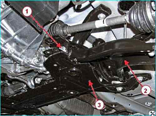
- - bolts 1, figure 33, fastening the front hinges of the arms 2 of the front suspension to the subframe 90 - 120 Nm (9 - 12 kgf.m);
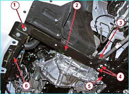
- - bolts 1, figure 34, fastening side members 2 to crossmember 6 of the radiator frame 18 - 24 Nm (1.8 - 2.4 kgf.m);
- - nuts 3 bolts 4 fastening side members 2 to subframe 5 of the front suspension 18 - 24 Nm (1.8 - 2.4 kgf.m).
Install mudguard 2, figure 10, of the engine and tighten thirteen bolts 1 of the fastening.
Check and, if necessary, adjust the installation angles of the front wheels.


