The hydraulic unit or hydraulic distributor, receiving signals from the electronic control unit, switches the channels in the control valve block and controls the clutch engagement pressure
Depending on the signal, one or another solenoid is triggered, and the fluid, flowing through the distributor channels, acts on the corresponding clutch mechanism.
We discussed the removal of the hydraulic distributor in the article - "Disassembling the DPO automatic transmission"
The hydraulic distributor (Fig. 1) consists of the upper and lower housing of the electromagnetic valves, separator plates, gaskets, electromagnetic pressure control valves, electromagnetic valve for locking up the torque converter and electromagnetic valves for sequential gear shifting.
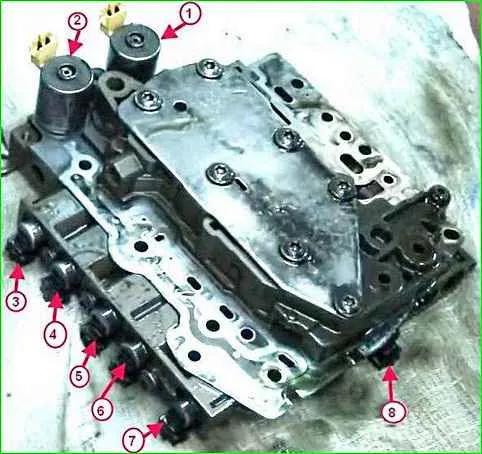
Repair of the hydraulic unit consists of replacing worn valves, seals on the solenoids, and flushing the hydraulic unit.
When working with the body of the control valves, be especially careful, as it consists of a large number of precision parts.
When removing, arrange the parts in a certain order so as not to mix them up.
Clean the removed parts with solvent and dry them with compressed air.
Clean all holes and channels with compressed air.
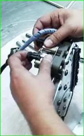
After removing the distribution block, disconnect the wiring harness from the valves (Fig. 2)
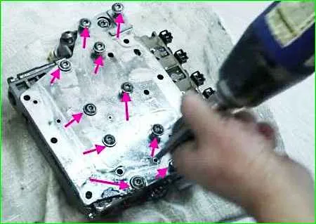
Unscrew the ten screws securing the lower cover of the block (Fig. 3) and remove it.
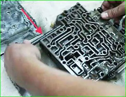
Remove the control rod (Fig. 4).
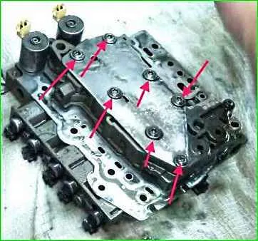
Turn the valve body over and unscrew the seven screws of the upper cover of the block (Fig. 5), and remove it.
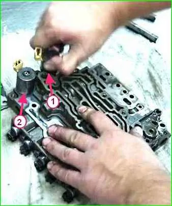
Remove the electromagnetic pressure control valve 1 (Fig. 6), and the electromagnetic valve of the torque converter lock-up (2).
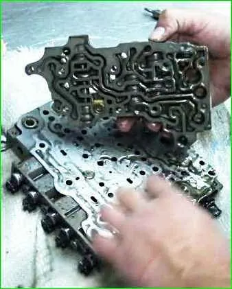
Remove the upper housing of the control valves (Fig. 7)
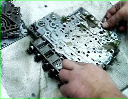
Remove the plate separator (Fig. 8)
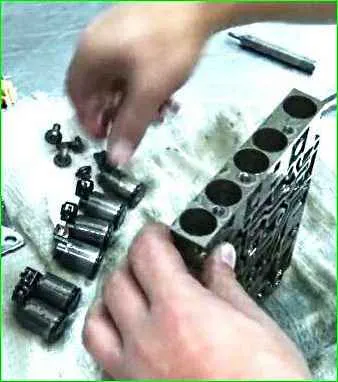
Unscrew the solenoids' mounting screws and remove the solenoids (Fig. 9)
Remove the rods and springs (Fig. 10)
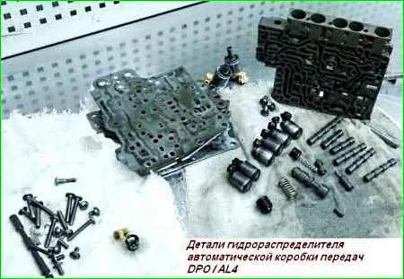
After disassembling, the block and all hydraulic distributor parts are washed.
Seals and defective parts are replaced.
Assemble the block in the reverse order.


