After removing the cylinder head, we disassemble it and inspect it for defects
Removing the cylinder head was discussed in the article - "How to remove the K4M cylinder head"

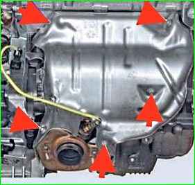
Removing the lower heat shield of the exhaust manifold (Figure 1).

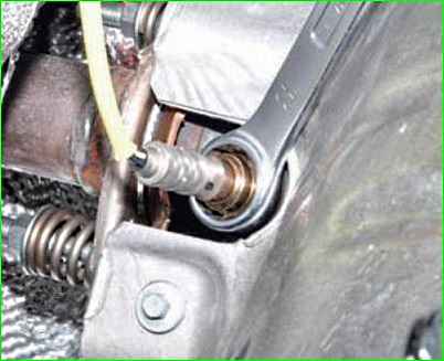
Put a 22 mm open-end wrench through the lambda probe wire and unscrew it.

Unscrew the fastening of the upper heat shield and remove it (Fig. 3 shows the screen with the cylinder head installed).

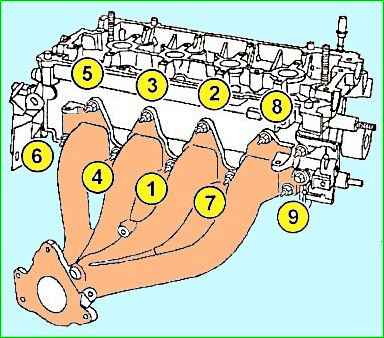
Removing the exhaust manifold (Figure 4).

Unscrew the thermostat unit from the cylinder head and remove it (Figure 5).

Remove the injector housing lining (see Fig. 6).

Compress the valve springs using the Mot1502 tool. The valve spring plate must fit into the bore (1) of the pressure sleeve (3) of the Mot1502 tool. (See Fig. 7).
To properly compress the valve springs, center the plunger (2) of the tool on the valve stem.
Remove the crackers, valve spring retainers, valve springs, valves and valve stem seals using Mot1335 pliers.
Removing the exhaust valve tappet

Bring the pin (3) of the Mot1669 tool to the stop (B) at the end of the guide groove by unscrewing the screw (4) (see Fig. 8).
Install the Mot1669 tool on the cylinder head by correctly inserting the guide pin (1) into the hole (2) of the cylinder head cover (see Fig. 8).

Secure the tool Mot1669 on the cylinder head cover with three bolts (see 3, Fig. 9).
Tighten the screw (1) until the pin (2) stops at point (A) at the end of the guide groove.

Unscrew the pusher lock bolt (see arrow, Fig. 10).
Turn out the screw (1) until the pin (2) is against the stop at point (B) at the end of the guide groove (see Fig. 9).
Remove the Mot1669 tool from the cylinder head cover.
Remove the tappet and spring.
Installing the exhaust valve tappet

Install the spring and tappet, aligning the groove (1) of the tappet with the hole (2) in the cylinder head cover (see Fig. 11).
- - bring the pin (3) of the Mot1669 tool to the stop at the end of the guide groove, unscrewing the screw (4) (see Fig. 8).
- - install the Mot1669 tool on the cylinder head, correctly inserting the mounting pin (1) into the hole (2) of the cylinder head cover (see Fig. 8).
- - Secure the Mot1669 tool to the cylinder head cover with three bolts (see 3, Fig. 9).
- - Tighten the screw (1) until the pin (2) is brought to the stop at the point (A) at the end of the guide groove.

- - Screw the hexagonal head bolt of the Mot1669 tool into the cylinder head cover to lock the tappet (see arrow, Fig. 12).
- - Unscrew the screw (1) until the pin (2) is brought to the stop at point (B) at the end of the guide groove (see Fig. 9).
- - Remove the Mot1669 device from the cylinder head cover.
The cylinder head is assembled in the reverse order, after the defect detection and repair of the cylinder head.


