Removal and disassembly of the engine cylinder head is discussed in the relevant articles.
After disassembling the cylinder head, you need to wash all the parts of the head, clean them from carbon deposits.
Prepare the parts for inspection.
Check the seating surface of the head and the height of the cylinder head.
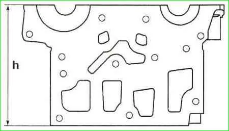
The height h of the block head should be 137 mm (Figure 1).
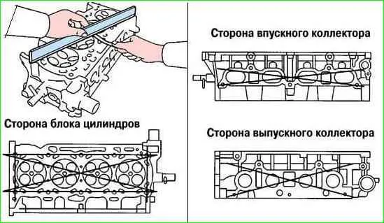
Using a ruler and feeler gauge, we check the non-flatness of the cylinder head mounting surfaces (Figure 2).
The maximum non-flatness allowed is 0.05 mm. Surface grinding is not allowed.
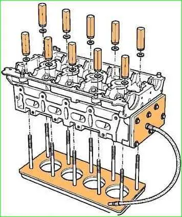
We check the cylinder head (absence of cracks and through corrosion) using the appropriate device (Figure 3).
We check the length of the head mounting bolts. The length of the bolts excluding the head should not exceed 117.7 mm.
If we install new bolts, they do not need to be lubricated before installation; used bolts should be lubricated with engine oil.
Subsequent tightening of the cylinder head bolts is not required and is not allowed, otherwise the probability of the bolts breaking when unscrewing increases sharply.
Before tightening the bolts, remove any dirt and oil that remains in the threaded holes of the cylinder block.
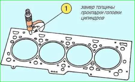
We measure the thickness of the gasket (Figure 4). The thickness is measured in the place indicated by the arrow in Figure 4.
The thickness of the new gasket should be 0.96±0.06 mm; the thickness of the compressed gasket should be 0.90±0.02 mm.
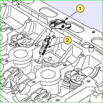
Inspect the hydraulic tappets and rocker arms.
Measure the valves in accordance with Figure 6.
The valve sizes must correspond to the data in the table.
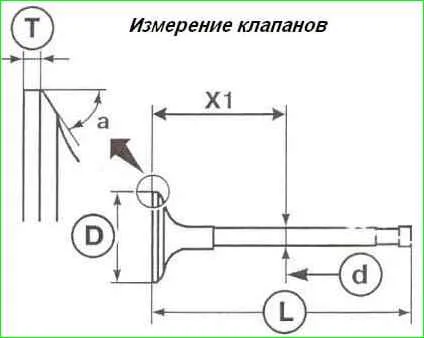
Main valve dimensions
Name Size mm.
Stem diameter D1:
- Intake valves 5.470-5.485*
- Exhaust valves 5.456-5.471*
Head diameter D2:
- Intake valves 32.70±0.12
- Exhaust valves 27.96±0.12
Valve length L:
- Intake valves 109.32
- Exhaust valves 107.64
Working chamfer angle A:
- Intake valves 45˚ 45′
- Exhaust valves 45˚
Minimum thickness of the cylindrical belt of the valve plate T:
- Intake valves 1.15
- Exhaust valves 1.27
Stroke valves:
- Intake valves 9.221
- Exhaust valves 8.075
* the diameter D1 of the valve stem is measured at a distance X1
- Intake valves X1 = 75.14±0.35 mm;
- Exhaust valves X1 = 77.5±0.35 mm;
Valve guides
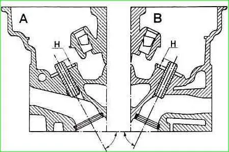
The inclination of the intake valve guide is 63˚30′ (Figure 7).
The inclination of the exhaust valve guide is 66°.
The height of the protruding part of the valve guide H is 11±0.15 mm for the intake and exhaust valves.
Valve seals
The valve seals are removed using the Mot1335 tool.
The valve seals are installed using the Mot1335 tool Mot1511 bleaching.
The valve stem seals must not be lubricated before installation.
Install the valve stem seals according to the instructions in Figure 8.
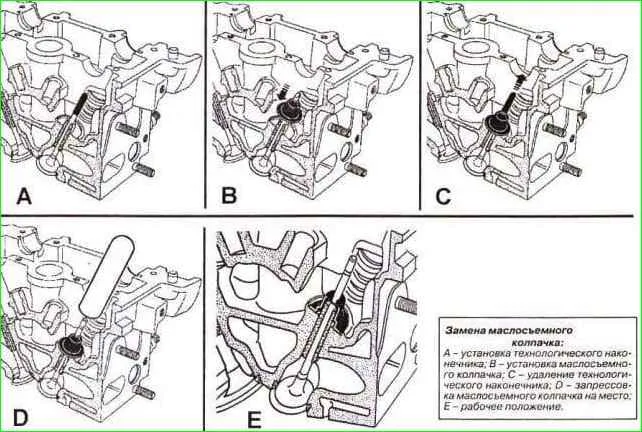
- - Insert the valve into the cylinder head cylinders.
- - Place the tip of the Mot1511 tool on the valve stem (the inside diameter of the tip should be equal to the diameter of the stem) (see Fig. 8).
- - Press the valve onto the seat.
- - Install the ungreased valve stem seal onto the tip.
- - Slide the valve stem seal through the tip.
- - Remove the tip.
- - Install the drift onto the valve stem seal. The inside diameter of the mandrel should match the diameter of the valve stem.
In addition, the lower part of the mandrel should partially rest against the valve stem seal, on the surface of which the valve spring washer rests.
- - Carefully press on the valve stem seal by tapping the upper part of the mandrel with your palm until the valve stem seal touches the cylinder head (see E, Fig. 8).
- - Repeat the above operations for all valves.
Checking valve springs
Spring defects are shown in Figure 9.
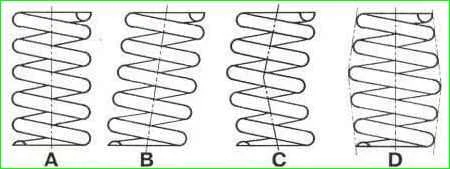
With deformations B and C, the spring can be used if the deviation from the vertical is no more than 1.2 mm, with loss of shape (D) - the spring must be replaced.
Even if the spring shape is preserved, its mechanical properties must be checked (height under a certain load).
Only after such a check is the suitability of the spring for further operation determined (see table).
Valve spring parameters
Parameter - mm
Height in a free state 41.30
Height of the spring in working condition 23.20
Inner diameter 18.80±0.20
Outer diameter 27±0.2
Wire cross-section - Oval
Height / under load
- 34.50/180-200
- 24.50/563-617
If you have a new spring, you can compare its characteristics with the characteristics of the old springs.
Install the new and old springs one after the other through the washers on the long bolt.
Tighten the bolt nut so that the height of the new spring decreases by 10 mm.
Measure the height of the old springs.
If the height of the old spring has decreased from 9 to 11 mm (±10%), it will still serve; if more, replace the old spring.
Checking the valve clearance in the guide sleeve
The clearance between the valve stem and the valve guide sleeve can be checked in two ways.
First method
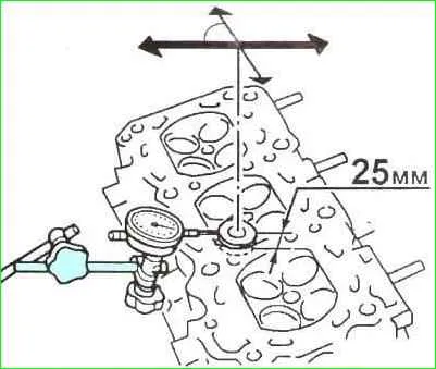
Lift the head valve by 25 mm, then measure the valve movement in the direction of the arrows with an indicator (see. fig.10) at an angle of 90˚ to the camshaft axis.
Half of the resulting value will give the value of the gap between the stem and the valve guide.
Second method
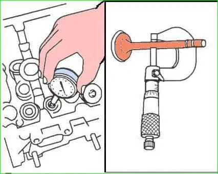
Measure the diameter of the valve stem and the inner diameter of the guide (see fig. 11).
Nominal gap, mm:
- - intake valves 0.015-0.048;
- - exhaust valves 0.029-0.062.
Checking camshafts
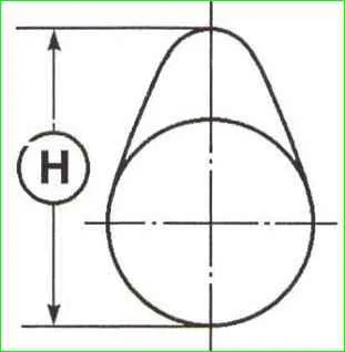
Height of cams H (see Fig. 12) camshafts must comply with the data in the table.
Camshaft dimensions
Parameters mm
Camshaft axial clearance:
- inlet and outlet valves 0.080-0.178
- Diametric clearance in the bearing ah 0.040-0.082
- Number of supports 6
Diameter of camshaft journals (see Figure 14):
- - journals No. 1; 24.979-25.000
- - journals No. 2, 3, 4, 5; 24.979-25.000
- - Neck No. 6 27.979-28.061
Height of cams H (Fig. 12):
- - Intake valves 40.661±0.030
- - Exhaust valves 40.038±0.030
Otherwise, replace the camshaft or perform a refurbishment.
The main dimensions of the camshafts are given in the table.
- - Check the clearance of the camshaft journals in the cylinder head supports, for this;
- - Install the cylinder head cover in place, tighten the bolts of its fastening with the standard torque tightening.
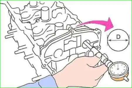
- Use a bore gauge to measure the diameters of all the holes in the camshaft supports (see Fig. 13), write down the measurement results.
Note. Measurements should be taken in the vertical plane of maximum wear.
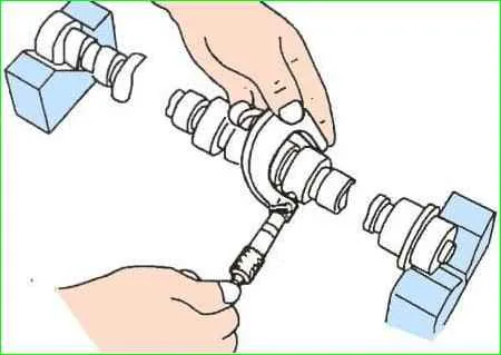
- Use a micrometer to measure the diameters of the camshaft bearing journals (see Fig. 14).
Measurements should be taken on each journal in two perpendicular planes. Take the lowest value on the journal as the base.
- Compare the measurement results with the maximum permissible values.
Then calculate the clearances for all journals and compare the obtained values with the maximum permissible values.
Based on the results:
- replace the camshaft, cylinder head, or both.
Note. If the camshaft and cylinder head are worn out, a restorative repair (spraying with subsequent processing) is possible.
Often the price of such repairs is much cheaper than buying new parts.
- If previous checks did not show the need to replace parts, then check the axial clearance of the camshafts, as described below, if necessary, replace the worn parts.
If the parts are new, still carry out the check, it is not difficult, but it is important to be sure of the results of the repair.
- - Install the camshafts, ensuring their correct position.
- - Install the cylinder head cover.
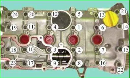
- - Tighten in the order shown in Fig. 15, the required torque:
- - cylinder head mounting bolts 13, 20, 22, 23, Nm 8;
- - cylinder head cover mounting bolts 1 through 12, 14 through 19 and 21 through 24, Nm 12.
- - Loosen head cover bolts 13, 20, 22, 23.
- - Tighten cylinder head cover bolts 13, 20, 22, 23 in the specified order to a torque of 12 Nm.
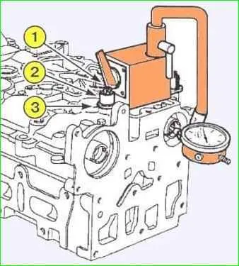
Fix the magnetic stand of the Mot588 axial clearance tester on the cylinder head using the mounting plate (3) of the Mot588 tool, tighten it with the oil separator mounting bolts (1) and spacers (2) with the following dimensions (see Fig. 16):
- - outer diameter, mm - 18;
- - bolt hole diameter, mm - 9;
- - height, mm - 15.
- - Check the axial clearance of the camshaft, which should be within 0.080-0.178 mm.
- - Remove the cylinder head cover and camshafts.


