With the ignition off, disconnect the wiring harness block of the engine management system of the mass flow sensor
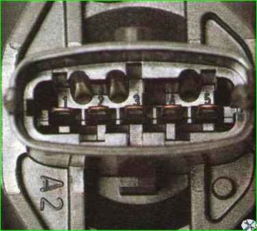
The wiring harness block pins “3”, “4” and “5” are marked inside the sensor connector.
Pin “1” of the block is connected to pin “40” of the controller - air temperature sensor signal input.
Pin “2” is connected to the main relay of the control system.

Pin “3” is connected to pin “36” of the controller - sensor grounding.
Pin “4” is connected to pin “33 controllers - power supply to the mass air flow sensor.
Pin “5” is connected to pin “37” of the controller - signal input of the mass air flow sensor.

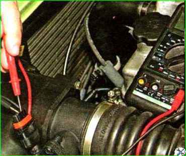
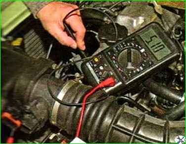
With the ignition on, use a tester to measure the voltage between the terminals of the block.
If the circuits are working properly, the tester should show the following values:
- - between pins “2” and “3” - more than 10 V;
- - between pins “3” and “4” - 4.8 - 5.2 V;
- - between pins “1” and “3” - 4.8 - 5.2 V.
If the voltage does not match, it means there is an open circuit or short to ground somewhere.

The resistance between terminal “5” of the control system wiring harness block and ground should be within 4 - 6 kOhm.
If the resistance is about 0 Ohm, then the sensor signal circuit is shorted to ground.
If the resistance is more than 100 Ohms, then there is a break in the sensor signal circuit or the controller is faulty


