We carry out the work with an assistant on an inspection ditch or overpass
Draining the oil from the gearbox
Disconnect the wire terminal from the negative terminal of the battery.
Remove the air filter.
Remove the starter.
We remove the clutch cable lead from the groove of the clutch release fork lever.
Remove the left mudguard of the power unit.
Disconnect the wire blocks from the reverse gear lock solenoid (see "Replacing the reverse gear lock solenoid"), from the reverse light switch and the speed sensor.
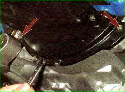
Using a 10mm wrench, unscrew the three bolts securing the lower cover of the clutch housing (Fig. 1).
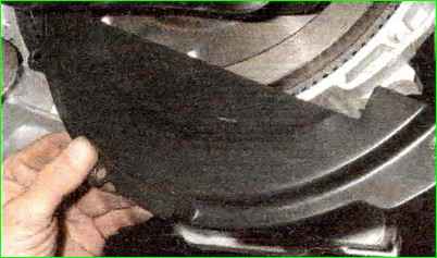
Remove the clutch housing cover (Fig. 2).
Remove the right and left front wheel drives.
Disconnect the transmission control rod from the shank of the gear selector rod hinge.
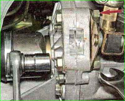
Using a 19mm wrench, unscrew the nuts of the two bolts securing the clutch housing to the gearbox housing (which also secure the torque rod bracket), holding the bolts from turning with a head of the same size (Fig. 3).
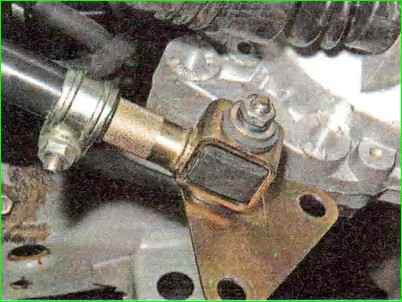
We remove the torque rod with the bracket from the gearbox (Fig. 4).
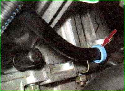
Disconnect the plastic throttle cable holder from the gearbox bracket (Fig. 5).
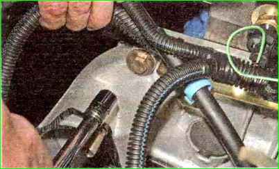
Using a 13mm socket, unscrew the bolt securing the ignition coil bracket to the clutch housing (Fig. 6).
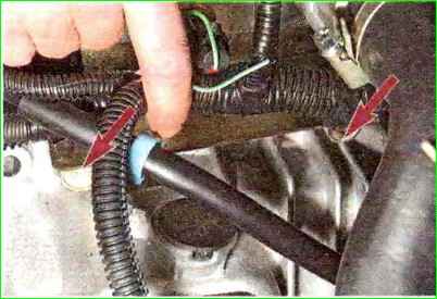
Using a 19mm socket, unscrew the two upper bolts securing the gearbox to the cylinder block (Fig. 7), which simultaneously secure the bracket with the holders of the throttle cable and wiring harness.
The front bolt (in the direction of vehicle travel) is shorter than the rear one.
We remove the bracket with the cable and wiring harness from the gearbox.
Remove the left front suspension brace.
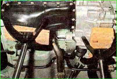
We install adjustable stops through wooden blocks under the engine oil pan and gearbox housing (Fig. 8).
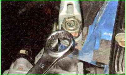
Using a 19mm spanner, unscrew the nut of the lower rear mounting of the gearbox to the cylinder block.
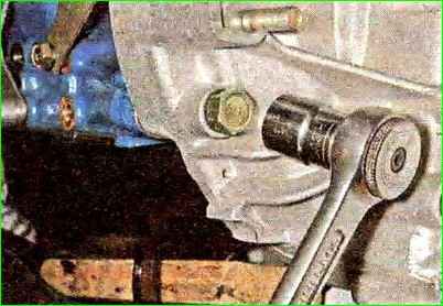
Using a 19mm socket, unscrew the bolt of the lower front fastening of the gearbox to the cylinder block.
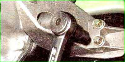
Using a 14mm socket, unscrew the two screws securing the front left support of the power unit to the support.
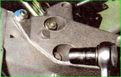
Using a 15mm socket, unscrew the three nuts securing the bracket for the front left support of the power unit to the gearbox
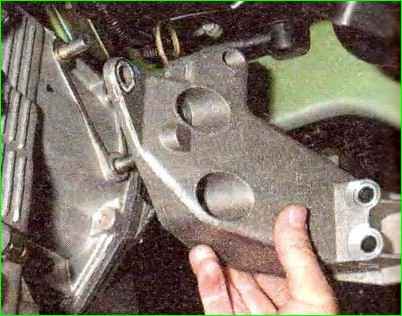
Remove the bracket (Fig. 13)
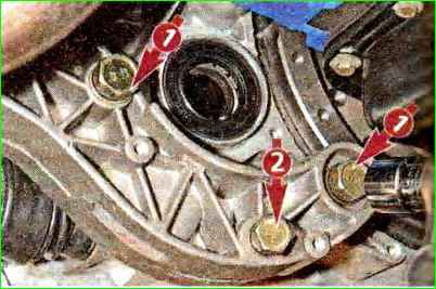
Use a 19 socket to unscrew the two outer bolts 1 securing the rear support bracket of the power unit to the gearbox, and use a 17 socket to unscrew the middle bolt 2 (Fig. 14).
We remove the gearbox from the engine, removing the input shaft from the hub of the driven clutch disk (Fig. 15).
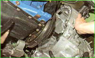
When removing and installing the gearbox, do not rest the gearbox input shaft on the clutch diaphragm spring petals to avoid damaging them.
Before installing the gearbox, apply a thin layer of CV joint-4 grease to the splined end of the input shaft.
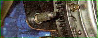
To facilitate the operation of installing the gearbox, screw two guide pins M12x1.25 mm (with sawn slots for a screwdriver) into the front lower threaded hole of the cylinder block and into the rear upper hole.
Insert the gearbox input shaft into the splines of the driven clutch disk and, orienting the gearbox so that the two guide pins fit into the corresponding holes in the clutch housing, and the standard clutch housing pin into the hole in the cylinder block, pushing the gearbox all the way into the cylinder block engine.
Use a screwdriver to unscrew the guide pins from the holes in the cylinder block.
We carry out further assembly operations in reverse order.
Pour oil into the gearbox.


