The car is equipped with two braking systems - working and parking
The service braking system is designed to reduce the speed of the vehicle, up to its complete stop and briefly hold the vehicle stationary.
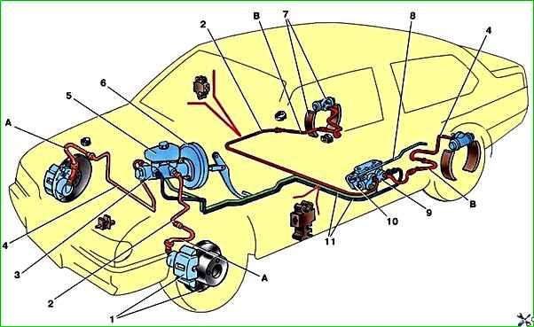
The service brake system is dual-circuit, diagonal, hydraulically driven, and consists of a master cylinder with a vacuum booster, four wheel brakes and a fluid pressure regulator in the rear brakes.
The front wheel brakes are ventilated disc, the rear wheels are drum.
Each of the car’s circuits includes brake mechanisms of two wheels: one front and one rear, located diagonally on the car.
One circuit includes the brake mechanisms of the front right and rear left tracks, and the second circuit includes the brake mechanisms of the front left and rear right tracks.
If one of the circuits fails, the second circuit, although with less efficiency, will ensure the vehicle stops.
The fluid pressure regulator limits the flow of fluid to the rear brake mechanisms when there is insufficient load on the rear axle, thereby preventing the rear wheels from locking and the rear axle of the vehicle from skidding during heavy braking.
The regulator body has a control hole closed with a plastic plug.
Liquid leakage from this hole indicates leakage of the regulator rings.
To reduce the force applied by the driver to the brake pedal, a vacuum booster is installed in the brake system drive, which operates due to the vacuum formed in the intake manifold of a running engine.
A brake fluid reservoir is installed on the brake master cylinder body.
A sensor for insufficient brake fluid level is built into the lid of the bank. If the liquid level in the tank drops dangerously, the sensor turns on the warning lamp on the instrument panel.
Some cars are equipped with a braking system with ABS (anti-lock braking system).
Possible brake malfunctions and methods of elimination
- Cause of malfunction
Elimination method
Increased brake pedal travel:
- Leakage of brake fluid from the wheel cylinders
Replace failed parts of the wheel cylinders, wash and dry the pads, discs and drums, bleed the hydraulic drive system
- Air in the brake system
Remove air from the system - article "How to bleed a car's brake system"
- The rubber sealing rings in the master brake cylinder are damaged
Replace the rings and bleed the system
- Rubber hoses for hydraulic brakes are damaged
Replace the hoses and bleed the system
- Increased runout of the brake disc (more than 0.15 mm)
Sand the disc; if the disk thickness is less than 10.8 mm, replace it
- Fluid leakage through the O-rings of the pressure regulator pusher
Replace the O-rings
Insufficient braking efficiency:
- Oiling of brake pad linings
Clean the pads with a wire brush using warm water and detergent. Eliminate the cause of fluid or grease getting on the brake pads
- Piston jamming in wheel cylinders
Eliminate the causes of jamming, replace damaged parts, bleed the system
- Complete wear of the brake pad linings, article - “How to repair rear wheel brakes”
Replace the brake pads
- Overheating of brake mechanisms
Stop immediately and let the brakes cool
- Using pads with mismatched linings
Use only pads recommended by the manufacturer
- Incorrect pressure regulator adjustment
Adjust the pressure regulator drive
- Loss of tightness of one of the circuits (accompanied by partial failure of the brake pedal)
Replace damaged parts, bleed the system
Incomplete release of the brakes on all wheels:
- There is no free play in the brake pedal
Adjust the pedal free play
- The protrusion of the adjusting bolt of the vacuum booster rod relative to the mounting plane of the master cylinder is impaired
Adjust the protrusion (1.25-0.2 mm) of the adjusting bolt
- Swelling of the rubber seals of the master cylinder due to gasoline, mineral oils, etc. getting into the liquid.
Thoroughly rinse the entire system with brake fluid, replace rubber parts, bleed the hydraulic drive system
- Main cylinder piston jammed
Check and, if necessary, replace the main cylinder, bleed the system
Braking one wheel with the brake pedal released:
- The tension spring of the rear brake pads is broken or weakened
Replace the spring
- Piston jamming in the wheel cylinder due to contamination or corrosion of the cylinder body
Disassemble the cylinder, clean and rinse parts, replace damaged ones, bleed the system
- Swelling of the o-rings of the wheel cylinder due to gasoline, mineral oils, etc. getting into the liquid.
Replace the rings, flush the brake hydraulic system with brake fluid, bleed the system
- Violation of the position of the caliper relative to the brake disc when loosening the bolts securing the pad guide to the steering knuckle
Tighten the fastening bolts, if necessary, replace damaged parts, article - “Repair of the front wheel brake mechanism”
- Incorrect adjustment of the parking brake system
Adjust the parking brake system
The car skids or pulls to the side when braking:
- Wheel cylinder piston jammed
Check and eliminate jamming of the piston in the cylinder, replace damaged parts if necessary, bleed the system
- Blockage of any steel tube due to dent or blockage
Replace the tube or clean it and bleed the system
- Contamination or oiling of discs, drums and linings
Clean the brake parts
- Incorrect adjustment of the pressure regulator drive
Adjust the drive
- Pressure regulator is faulty
Repair or replace the regulator
- Wheel alignment angles are broken
Adjust the wheel alignment
- Different tire pressures
Set normal pressure
- One of the brake system circuits does not work (accompanied by deterioration in braking efficiency and increased pedal travel)
Replace damaged parts and bleed the system
Increased force on the brake pedal when braking:
- The vacuum booster is faulty
Replace the amplifier
- The hose connecting the vacuum booster and the engine intake pipe is damaged, or its fastening to the fittings is loose
Replace the hose or tighten its fastening clamps
- Swelling of cylinder seals due to gasoline, mineral oils, etc. getting into the liquid.
Rinse the entire system thoroughly, replace rubber parts, bleed the system
Squeaking or vibration of brakes:
- Weakening the tension spring of the rear brake pads
Check the tension spring, replace it with a new one if necessary
- Ovality of brake drums
Bore the drum
- Oiling the friction linings
Clean the pads with a wire brush using warm water and detergent.
Eliminate the cause of fluid or grease getting on the brake pads
- Wear of the linings or inclusion of foreign bodies in them
Replace the pads
- Excessive runout of the brake disc or uneven wear (felt by vibration of the brake pedal)
Grind the disc, if the thickness is less than 10.8 mm, replace it
Basic system data:
- Brake fluid type - DOT 4
- filling volume of hydraulic brake system 0.45 l
- Free play of the brake pedal 3-5 mm
- Number of clicks of the parking brake ratchet 2-4
- The minimum thickness of the friction linings of the front brake pads is 1.5 mm
- Minimum brake disc thickness 17.8 mm
- Maximum brake disc runout 0.15 mm
- Maximum diameter of the working surface of the brake drum 201.5 mm
- The minimum thickness of the friction linings of the rear brake pads is 1.5 mm
Tightening torques for threaded connections:
Name of components – Thread - Tightening torque, Nm (kgf-m)
- Wheel mounting bolts M12x1.25 - 65.2-92.6 (6.7-9.5)
- Nut securing the vacuum brake booster bracket to the M8 body - 31-38 (3.2-3.9)
- Nuts securing the vacuum brake booster to the bracket M10 - 26.5-32.3 (2.7-3.3)
- Nuts securing the brake master cylinder to the vacuum booster M10 - 26.5-32.3 (2.7-3.3)
- Front wheel brake hose end M10x1.25 - 29.4-33.4 (3.0-3.4)
- Bolts securing the front wheel brake mechanism to the steering knuckle M10x1.25 - 29.1-36 (3.0-3.7)
- Bolts securing the front brake working cylinder to the guide pins M8 - 31-38 (3.2-3.9)
- Bolts securing the front brake working cylinder to the caliper M12x1.25 - 95.9-118.4 (9.8-12.1)
- Brake pipe fittings M10 - 14.7-18.2 (1.5-1.9)
- Bolt for fastening the working cylinder of the rear brake mechanism M6 - 3.3-7.7 (0.3-0.8)
- Nut for fastening the pressure regulator bracket M8 - 10.4-24.2 (1.1-2.5)
- Bolt securing the pressure regulator to the bracket M8 - 10.4-24.2 (1.1-2.5)
")

")
")
")
")
")
")
")