Turn off the ignition and disconnect the engine management system wiring harness block from the sensor

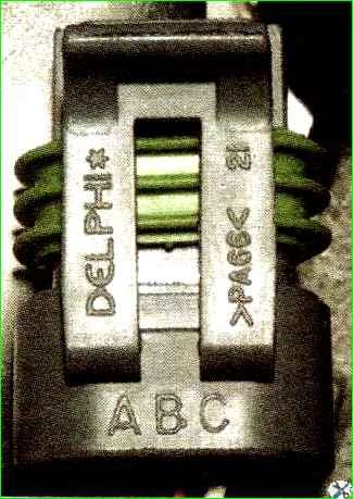
Wire markings “A”, “B”, “C” are marked on the plug body.

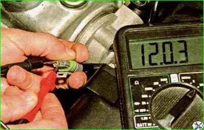
To check the sensor's power circuit, connect the tester to terminals "A" and "B". When the ignition is turned on and for 10 seconds after it is turned off, the voltage should be equal to the on-board network voltage.
If not, then check the serviceability of the circuits, most likely an open or short to ground between terminal “B” of the wiring harness plug and contact No. 45 of the controller, as well as between terminal “A” of the plug and the grounding point.
If the circuits are working properly and there is no voltage, the controller is faulty.

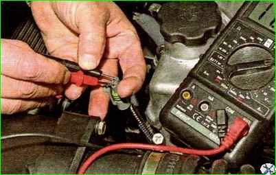
Connect the tester probes to terminals “C” and “A” of the wiring harness block.
When the ignition is on (and in the absence of a phase sensor signal), the controller, through its internal resistor, must output on-board network voltage to terminal “C” of the wiring harness block.
Otherwise, check the serviceability of the circuit (open and short to ground) between terminal “79” of the controller and terminal “C” of the wiring harness block.

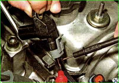
To check the phase sensor, dismantle it and connect the wiring harness block to the sensor.
From the side where the wires enter the block, insert two pieces of wire into its sockets corresponding to terminals “A” and “C”, so that contact appears between them and the tips of the wires.
Connect the tester probes to the pieces of wire.
After turning on the ignition, we bring a steel rod to the end of the sensor several times.
In this case, for a working sensor, the device should record abruptly changing voltage values.


