In this article we will look at disassembling the main gearbox components of a Lada Granta
We clean the dirt and wash the outside of the gearbox (do not allow water to get into the crankcase).
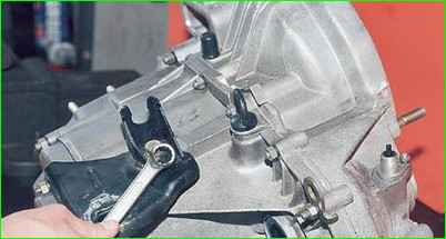
Using a 17" wrench, unscrew the bolt securing the power unit suspension bracket
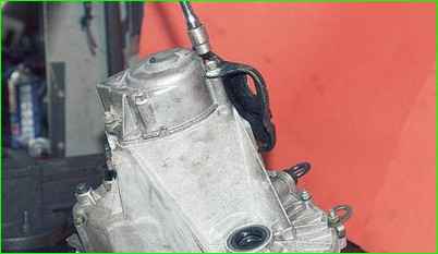
Using a 13" socket, unscrew the six nuts securing the rear crankcase cover.
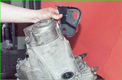
Remove the bracket.
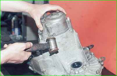
Tapping with a copper hammer (or an ordinary one through a soft metal mandrel) on the tides of the lid, remove it together with the sealing gasket from the studs.
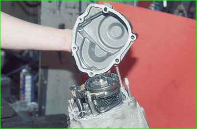
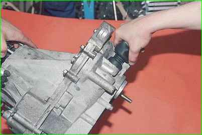
Pressing the gear selection rod all the way, engage third gear, or, retracting the rod all the way, engage fourth
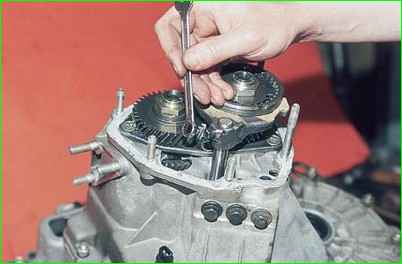
Use a 10mm spanner to unscrew the fifth gear fork mounting bolt
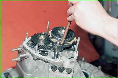
Using a soft metal drift, strike the fork downwards, including fifth gear
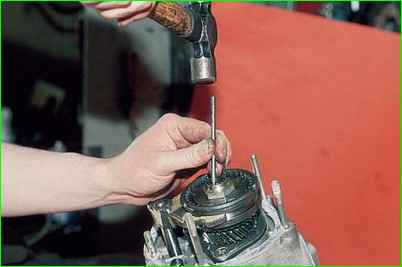
Use a beard to straighten dents in the nuts of the primary and secondary shafts
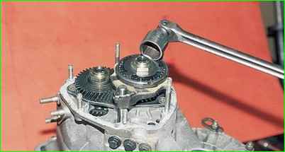
Use a 32" socket with a powerful wrench to unscrew the shaft nuts.
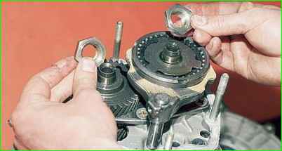
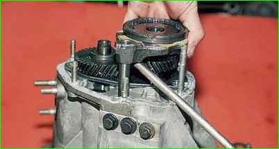
Using a screwdriver to pry up the fifth gear fork, remove the fifth gear assembly.
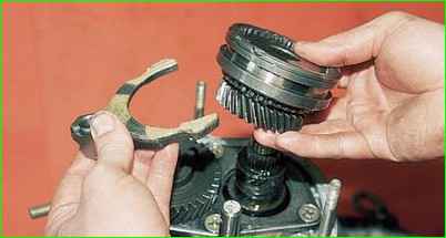
Remove the fifth gear shift fork.
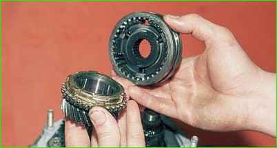
Remove the synchronizer sliding clutch with the hub
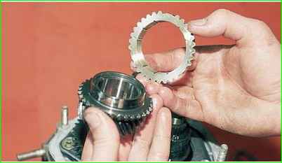
Remove the synchronizer blocking ring
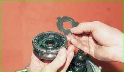
Remove the thrust plate
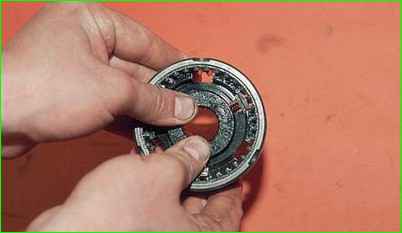
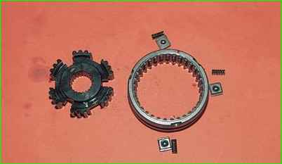
We move the hub inside the synchronizer sliding clutch and remove the hub, springs, clamps and fifth gear synchronizer blocks.
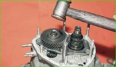
Use a copper hammer to strike the end of the input shaft.
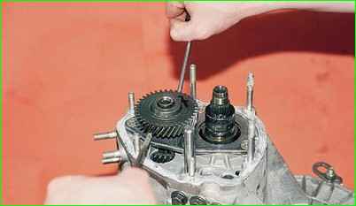
Insert two screwdrivers into the gap between the thrust plate and the fifth gear drive gear.
Prying up the gear with screwdrivers, we compress it.
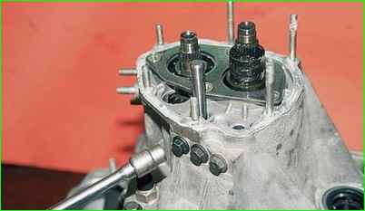
Using a 13mm socket, unscrew the three plugs of the gearshift rod clamps.
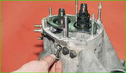
Remove the springs and retaining balls from the sockets
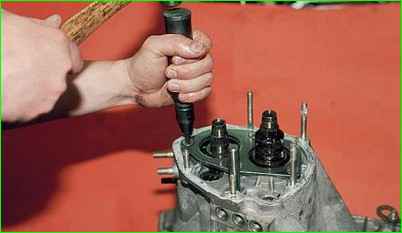
Use a Phillips impact screwdriver to unscrew the four screws securing the thrust plate.
The screws have special lock washers
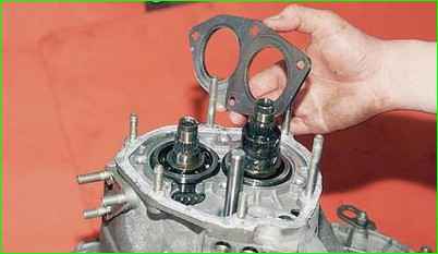
Remove the thrust plate
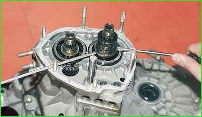
Use two screwdrivers to pry off the thrust washer of the fifth gear driven gear bushing
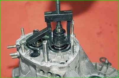
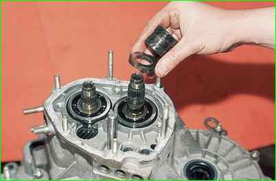
Insert the paws of the puller into the gap formed between the end of the rear bearing and the thrust washer and compress the gear bushing and the thrust washer.
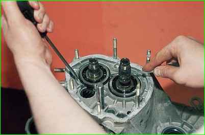
Use two screwdrivers to separate the retaining ring on the input shaft and remove it.
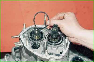
In the same way, remove the retaining ring from the secondary shaft.
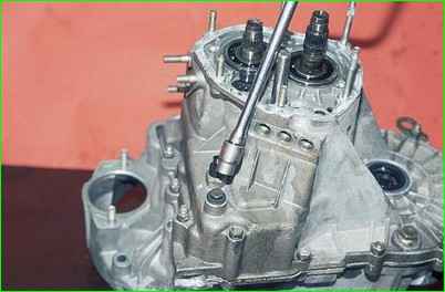
Use a 13mm socket to unscrew the reverse gear lock plug and remove the spring.
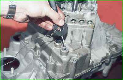
Insert a screwdriver into the socket of the latch and, applying a magnet to it, remove the ball.
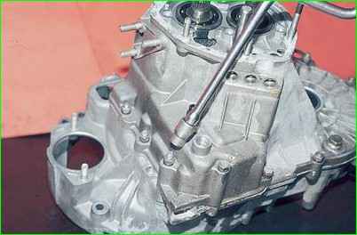
Use the “13” head to turn it off thirteen nuts and one bolt securing the gearbox housing to the clutch housing.
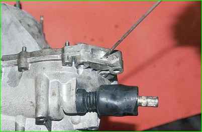
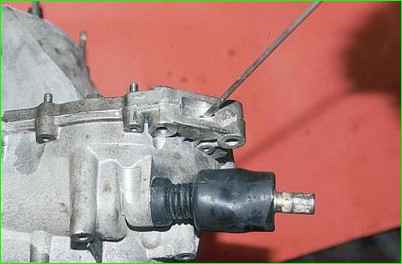
Inserting a screwdriver into the groove at the junction of the mating planes of the crankcases, carefully lift the box crankcase and remove it.
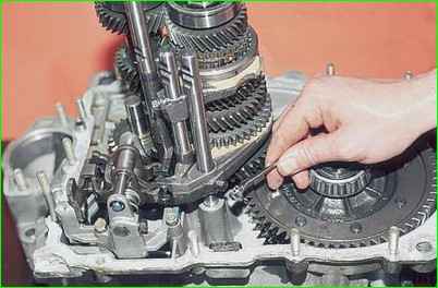
Using a 10mm spanner, unscrew the bolt securing the first and second gear fork to the rod
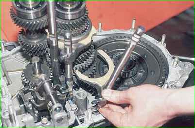
Lift the rod up and disengage the fork
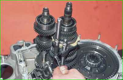
Using a 10mm spanner, unscrew the bolt securing the third and fourth gear fork to the rod
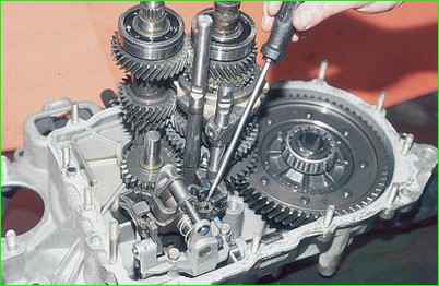
Use a screwdriver to remove the rod from the gear selection mechanism.
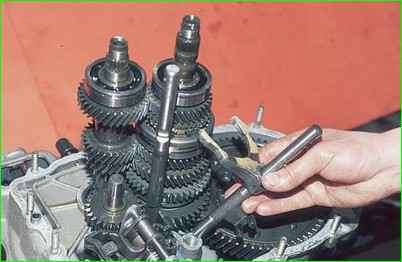
Lift the rod up and remove the fork from the groove of the synchronizer sliding clutch.
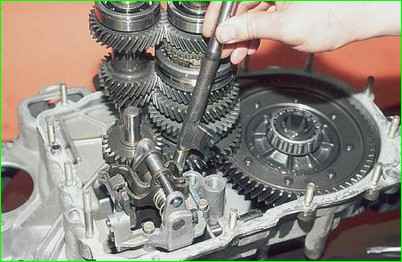
Turn the fifth gear engagement rod to remove it from the gear selection mechanism
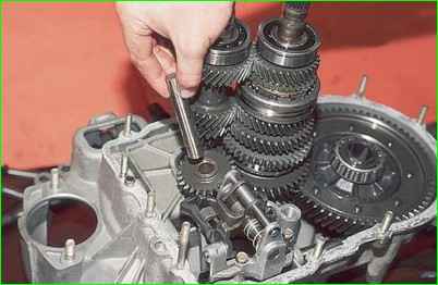
Remove the axis of the reverse intermediate gear.
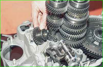
Remove the reverse intermediate gear
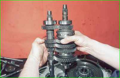
We simultaneously remove the primary and secondary shafts from the roller bearings of the clutch housing
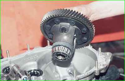
Take out the differential assembly.
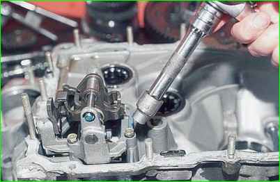
Using a 10mm socket, unscrew the three bolts securing the gear selection mechanism and remove it.
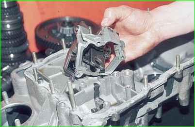
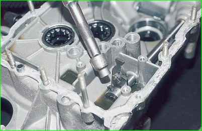
Use a 10mm socket to unscrew the installation bolt of the gear selector lever
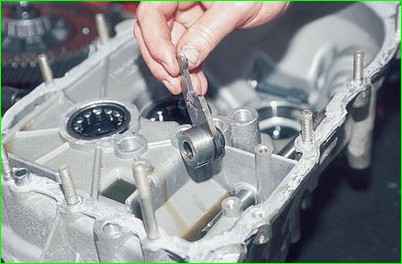
Remove the gear selector lever from the rod
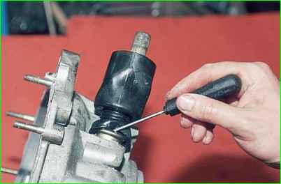
Using a screwdriver, remove the protective cover of the rod from the bushing
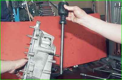
Remove the gear selector rod
You can replace the gear selector rod hinge on the gearbox installed on the car (you should not remove the joint from the rod unless necessary, since the fastening bolt is installed on a special TB-1324 glue).
For clarity, we carry out this operation on the removed rod.
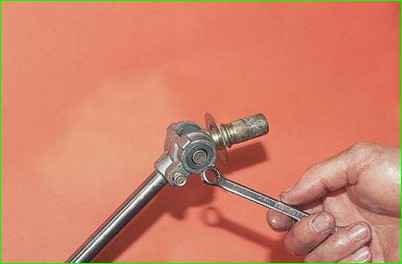
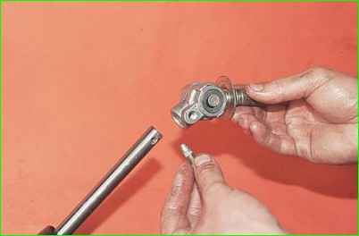
Use a 10mm spanner to unscrew the hinge mounting bolt and remove the hinge.
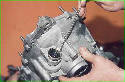
To replace the gear selector rod oil seal, pry it with a hook made of thick wire and remove it from the bushing
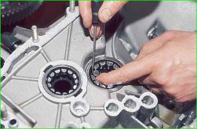
Use a screwdriver to remove the rollers of the front bearing of the secondary shaft from the separator
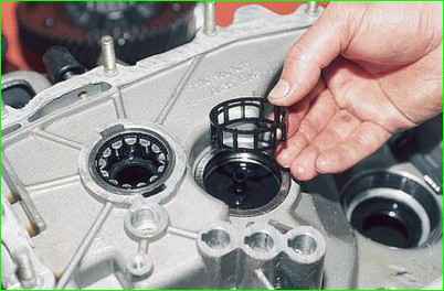
Remove the bearing cage
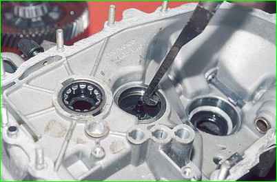
Hooking the hook of the device onto the shoulder of the outer ring of the bearing, press out the ring with blows on the hook.
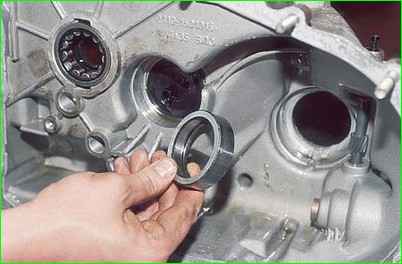
Remove the oil pan
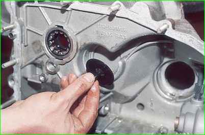
In the same way we press out the outer ring of the input shaft bearing.
Take out the magnet.
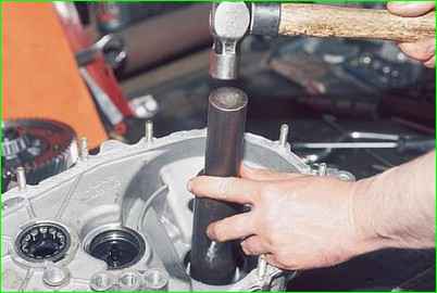
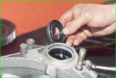
Use a suitable piece of pipe to knock out the drive oil seal from the clutch housing.
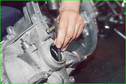
Through the bit we strike the end of the outer ring of the differential bearing and press out the ring.
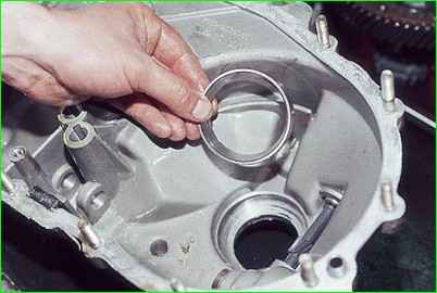
In the same way, we knock out the oil seal and the outer ring of the differential bearing from the gearbox housing.
Take out the adjusting ring.
Clamp the input shaft in a vice with soft jaws.
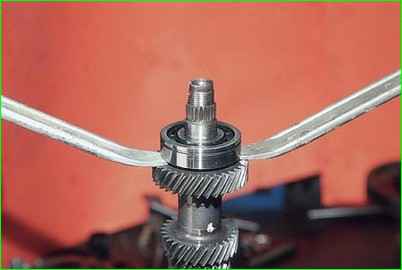
Pry up the rear ball bearing with two mounting blades and press it together
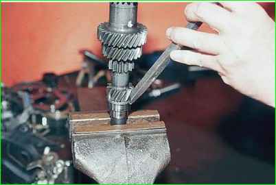
Through the mandrel we strike the end of the inner ring of the front bearing and compress the ring.
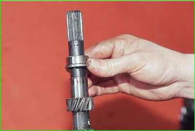
Clamp the secondary shaft in a vice with soft jaws
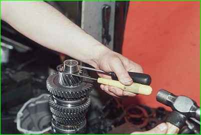
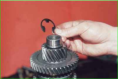
Use two screwdrivers to press against the ends of the retaining ring and remove it from the front end of the shaft.
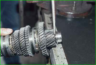
Insert a screwdriver into the gap between the inner ring of the front bearing and the end of the main gear drive gear and press out the ring.
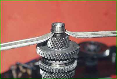
Insert two mounting blades into the resulting increased gap and press the inner ring of the bearing from the shaft.
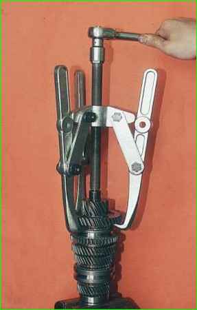
Having grabbed the driven gear of the first gear with a three-legged puller, we press the drive gear of the main gear.
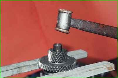
If there is no puller, place stops under the gear and strike the end of the shaft with a copper hammer.
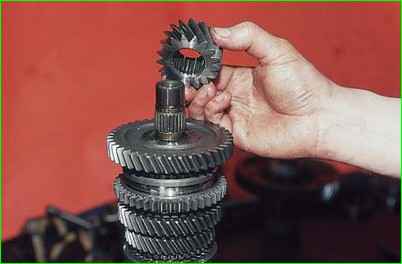
Remove the main gear drive gear.
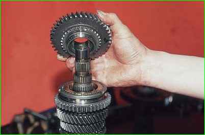
Remove the first gear driven gear.
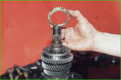
Remove the first gear synchronizer blocking ring
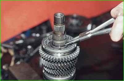
Using pliers, separate the locking ring of the synchronizer hub and remove it.
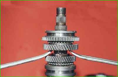
Prying the driven gear of the second gear with two mounting blades, we press the hub of the sliding clutch for the synchronizer of the first and second gears from the shaft.
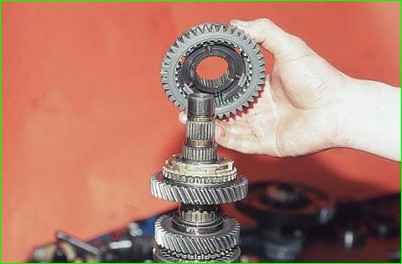
Remove the sliding clutch with the synchronizer hub and the second gear synchronizer blocking ring
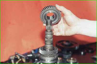
Remove the second gear driven gear.
Turn over the shaft in a vice.
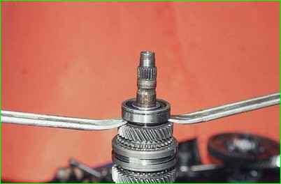
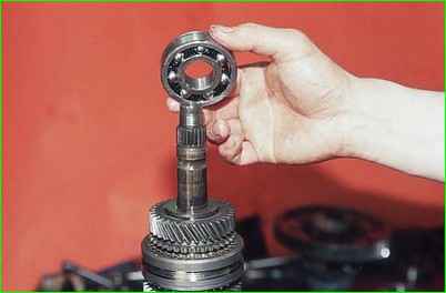
Prying up the rear bearing of the secondary shaft with two mounting blades, we press it.
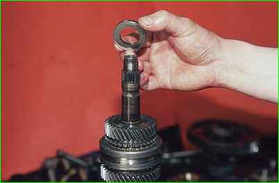
Remove the thrust washer.
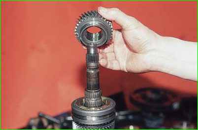
Remove the fourth gear driven gear.
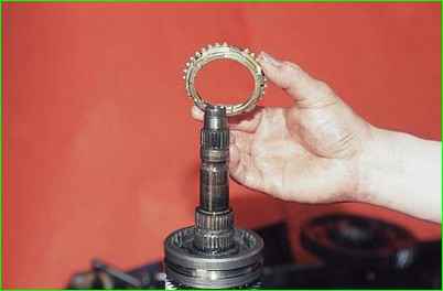
Remove the fourth gear synchronizer blocking ring
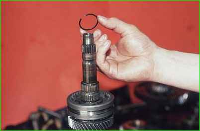
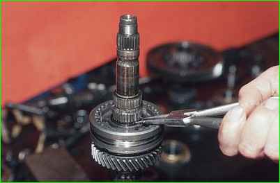
Using pliers, separate the locking ring of the synchronizer hub and remove it.
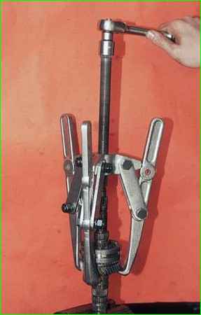
Having grabbed the third gear gear with a three-legged puller, we press the hub of the sliding clutch for the third and fourth gear synchronizer from the shaft
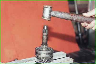
If there is no puller, place stops under the gear and strike the end of the shaft with a copper hammer.
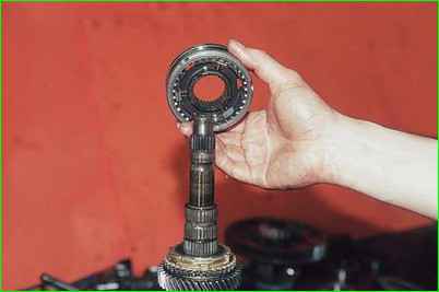
Remove the sliding clutch with the synchronizer hub
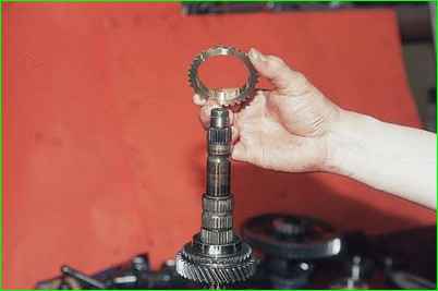
Remove the third gear synchronizer blocking ring
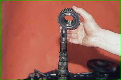
Remove the third gear gear.
Clamp the driven gear of the main drive in a vice with soft jaws.
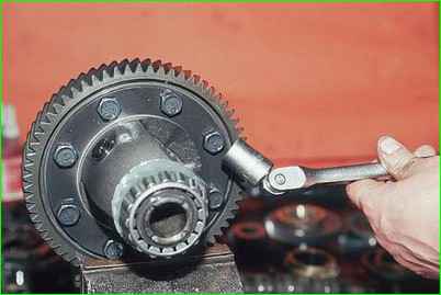
Using a 17" socket, unscrew the eight bolts securing the gear to the differential box.
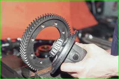
Use a copper hammer to knock out the differential box.
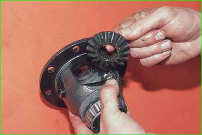
Turning, we remove the drive gears (semi-axial) from the box.
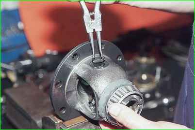
Holding the differential box in a vice, use round-nose pliers to remove the retaining ring from the pinion axis.
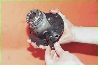
Press on the satellite axis and remove it from the box.
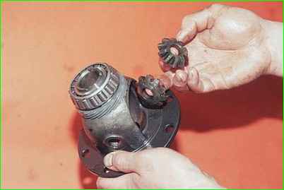
Remove the satellites from the box
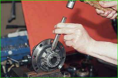
To remove the differential bearings, clamp the box in a vice.
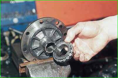
Inserting a chisel into the gap between the end of the inner ring of the bearing and the differential box, strike the chisel
Compress the bearing


