We fix the starter in a vise
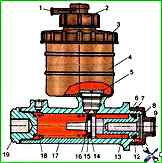
We unscrew the nuts, remove the jumper 10 connecting the relay and the housing

We unscrew the four nuts on the cover 6 from the side of the collector, fastening the traverse 5
Bending the lock washers 2, unscrew the four bolts 3 and remove the cover 6
We unscrew the screws 8 that fasten the leads of the excitation winding and brushes to the traverse. Remove brushes 7 and 9 and traverse 5
Removing two screws 17 from the flange, remove the axis 18 of the lever
We unscrew the four screws 15 and remove the relay 13 together with the relay armature
Bending back the lock washers 21, unscrew the bolts 20 securing the cover 16 from the drive side and remove the cover
Remove drive 19 and lever 14 from the cover
Remove bearing holder 22
Remove anchor 1 starter from housing 23
Rinse and dry starter parts
Checking the technical condition of parts
Not allowed on the starter housing:
- - soldering or breakage of contact connecting busbars;
- - wear of the surface of the poles;
- - broken pin tip
Solder soldered connecting bars
Remove damage to the insulation of the winding of the pole coils with a keeper tape
The broken tip of the contact terminal is replaceable. If the insulating washers or gaskets of the terminal are damaged, replace them
Clean out nicks and burrs on the seats of the covers
Anchor assembly. Not allowed:
- - curvature of the armature shaft more than 0.25 mm;
- - collector working surface diameter less than 52.26 mm;
- - twisting of shaft splines, shaft break;
- - closure of collector plates to each other;
- - dents on the collector surface;
- - closing the turns of the winding to the body or to each other;
- - protrusion of winding turns from the sleeve package
Remove curvature by editing under pressure
Remove wear and burning of the collector by turning
Eliminate the short circuit of the turns of the armature winding to the body or between each other by rewinding the winding or replacing the armature itself
Cover on the manifold side. Not allowed:
- - cracks on the lid;
- - the inner diameter of the bronze-graphite bushing is more than 16.3 mm;
- - salting the felt;
- - cover insulation burn-out;
- - brush height less than 13 mm;
- - pressure of brush springs on brushes more than 1.5-2.05 kgf;
- - the width of the brush holder groove is more than 12.25 mm
Drive side cover. Not allowed:
- - bummer of the boss bracket or starter attachment lug;
- - landing bead break;
- - the inner diameter of the bronze-graphite bushing is more than 19.4 mm;
- - salting the felt
Starter drive. Not allowed:
- - cracks or broken teeth of the drive wheel;
- - broken springs;
- - wheel teeth wear;
- - deformation of the lead-in of the teeth (eliminated by cleaning the ends and grinding the leads);
- - the outer diameter of the lever fingers is less than 11.5 mm
Starter relay. Not allowed:
- - bellows wear, relay cover melting, relay coil burning;
- - contact bolt height less than 3.5 mm;
- - the thickness of the contact disk is less than 3.5 mm
If necessary, clean the contact bolts and discs without disturbing the plane of the contact surfaces
Bearing holder assembly. Not allowed:
- - salting the felt;
- - cuff wear;
- - the inner diameter of the bronze-graphite bushing is more than 25.5 mm
Starter assembly
We fix the starter housing in a vise
Install the bearing holder 22 in the starter housing
Install anchor 1 starter in the housing
We install drive 19 on the splines of the armature shaft
We start the lever 14 in the drive
Install cover 16 on the drive side. We install new lock washers 21 and tighten with a torque of 6.28-7.75 Nm (0.64-079 kgcm) bolts 20 for fastening the cover on the drive side
We install the relay 13 with the lever 14 and fix it with screws 15 on the cover on the drive side with a torque of 2.94-4.4 Nm (0.3-0.47 kgcm)
We fix the excitation winding leads on the traverse 5
Install traverse 5 on the collector, put brushes 7 and 9 in the brush holders
The brushes should move easily, without jamming, in the brush holders and be lapped to the surface of the collector. The contact between the brushes and the commutator should be over the entire surface of the brushes
We install cover 6 on the side of the collector, install new lock washers 2 and screw in bolts 3 for fastening the cover with a torque of 6.28-7.75 Nm (0.64-0.79 kgcm)
We install and fix with nuts 11 and 12 the jumper 10 connecting the relay 13 and the starter housing 23. The tightening torque of nuts 11 is 17.6-21.6 Nm (1.8-2.2 kgcm), nuts 12 is2.94-4.4 Nm (0.3-0.47 kgcm)
We regulate the operation of the drive by turning the axis 18 of the lever, which has two (or six) adjustment grooves
For regulation:
- - when the relay is turned on, turn the flange of the axis 18 of the lever to ensure a gap of 0.5-1.5 mm from the washer on the armature shaft to the end of the drive guide. In this case, the grooves of the flange must match the threaded holes in the cover 16 on the drive side
- - screw in the screws 17 of the lever axle flange
The starter relay contacts must not be closed when the drive sleeve rests against the 6 mm thick gasket inserted between the drive guide and washer
The starter is tested on the stand
Specifications
Idling:
- - consumed current no more than 130 A;
- - voltage at the starter terminals is not more than 24 V
In braking mode:
- - consumed current no more than 800 A;
- - voltage at the starter terminals is not more than 18 V;
- - braking torque no more than 49 Nm (5kgcm)

")
")
")
")
")