The carburetor should be removed from the engine mainly to flush it from dirt and resins, since repairs and adjustments of most of its systems and elements can be carried out without dismantling
Withdrawal
Remove the air filter.
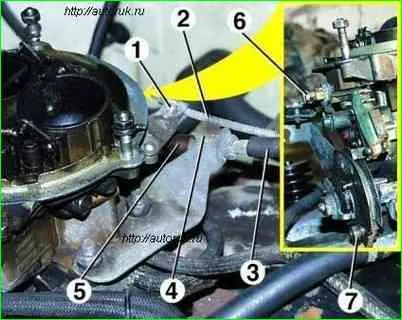
Unscrew screw 6 securing the rod 2 to the air damper drive lever, unscrew screw 1 securing the rod to the bracket and disconnect the rod from the carburetor
Unscrew nut 7 securing the accelerator cable to the throttle valve drive sector, move the oil seal 5, unscrew nut 4 and remove rod 3 from the bracket and throttle valve drive sector.
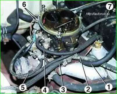
Having loosened the clamps, remove the fuel supply hoses 2 and drain 3 from the carburetor fittings, hose 1 of the crankcase ventilation system, the vacuum hose for controlling the forced idle economizer (EPHH) on the back side of the carburetor and hose 5 to the electromagnetic valve of the EPHH system, to the vacuum - to the ignition distributor corrector 7 and to the exhaust gas recirculation thermal switch 4
Disconnect wires 6 from the microswitch of the EPHH system.
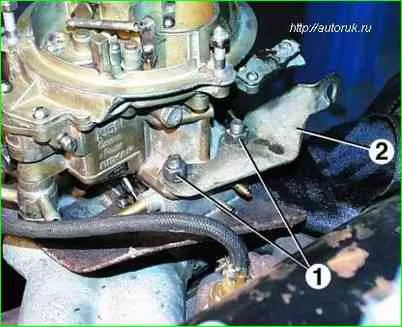
Unscrew the four nuts 1 securing the carburetor to the intake pipe, remove the cable holder 2 and dismantle the carburetor.
Disassembly
It is not recommended to unscrew the screws securing the throttle valves on the axles and remove the valves unless absolutely necessary, since their displacement can lead to jamming of the valves in the channels.
The brass connecting tubes of the channels pressed into the body should not be removed to avoid disturbing the tightness of their fit.
Disassemble the carburetor only as a last resort if washing and blowing with compressed air without disassembly does not eliminate sticking of the throttle and air valves and does not lead to complete cleaning of the jets and channels from deposits.
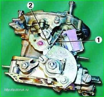
Disconnect rod 1 of the air damper drive from the profile lever by removing cotter pin 2 from the hole at its curved end.
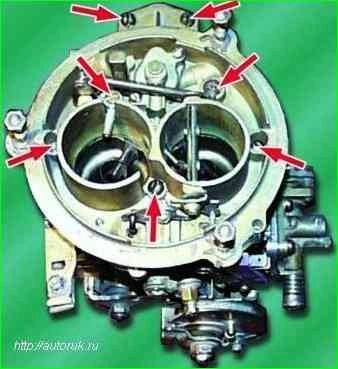
Remove the seven screws securing the cover to the body and remove the carburetor cover
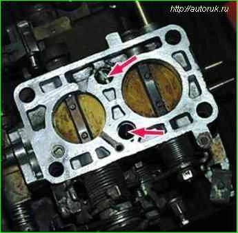
Unscrew the two screws securing the throttle body and, disengaging the connecting link, remove the body
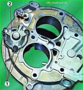
Unscrew the three fastening screws 1 and remove the cover 2 of the vacuum diaphragm of the carburetor starting device.
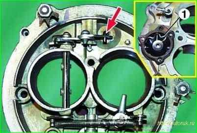
On the back side of the carburetor cover, remove the bent end of the carburetor trigger diaphragm rod from engagement with the trigger lever
Remove diaphragm 1 from the carburetor cover.
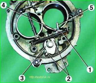
Disconnect tension spring 1 of the air damper from the cover pin
Unscrew the two screws 2 and remove the cover 3 of the float chamber ventilation channel
Unscrew the fastening screw 4 and remove the econostat sprayer 5.
Unscrew the mounting screws and remove the starter drive levers.
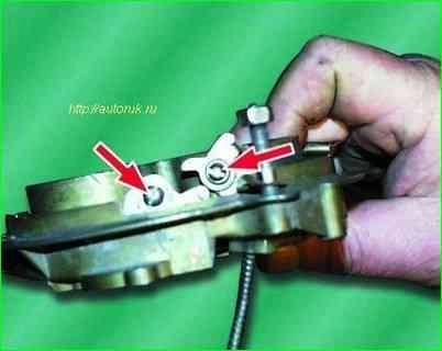
Carefully remove the heat-insulating gasket from the lower flange of the mounting housing.
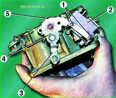
Unscrew the two screws 1 microswitch 2 of the EPHH system. Remove the cotter pin 4 and remove the air damper control lever 3 along with the profile lever 5 from the axis.
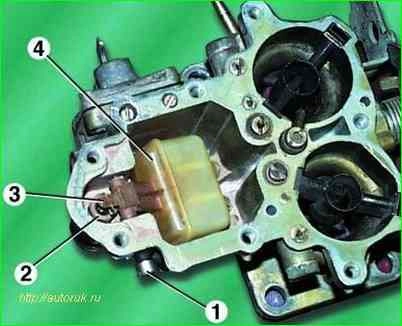
Use a screwdriver to unscrew plug 1 of the float axis hole and remove the aluminum sealing washer located underneath
Use tweezers or pliers to remove the float axis and remove float 4 and needle 3 of the shut-off valve
Unscrew seat 2 from the carburetor body.
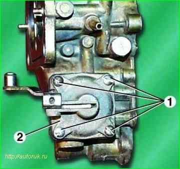
Unscrew the four fastening screws 1 and REMOVE the accelerator pump cover 2 together with the lever.
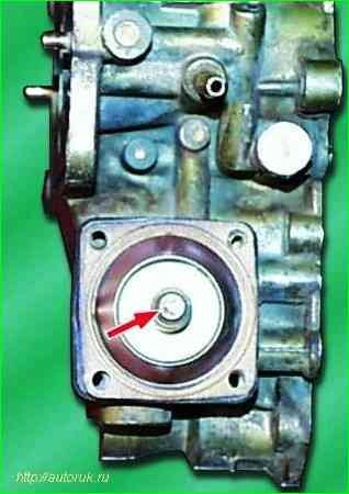
Remove the accelerator pump diaphragm and the release spring located underneath it.
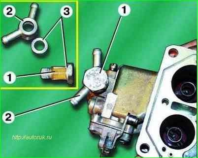
Unscrew the hollow fuel supply bolt 1 and remove it together with the manifold 2 and aluminum sealing washers 3
Remove the fuel supply bolt 1 from the manifold 2 together with the strainer and remove the aluminum sealing washers 3 from it.
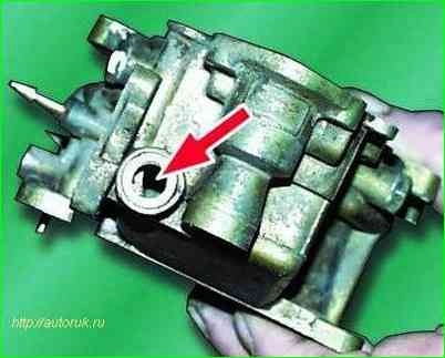
Unscrew the drain plug with the sealing washer from the wall of the float chamber.
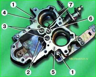
Using a carefully selected screwdriver (to avoid damage to parts made of brass), unscrew air 3 and fuel 2 jets of the main metering system, air jets 4 and 5 of the idle and transition system from the housing
Unscrew the screw plugs 1 located on the sides of the housing and unscrew the fuel nozzles of the idle speed system and the transition system located under the plugs
Unscrew the hollow fuel supply screw 6 securing the accelerator pump nozzle and remove the nozzle 7 together with the sealing aluminum washers.
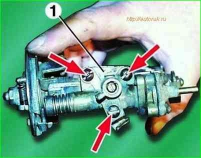
Unscrew the three fastening screws and remove block 1 EPHH together with the carburetor body gasket.
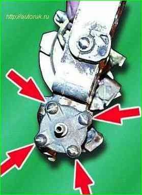
If it is necessary to replace the EPHH diaphragm, unscrew the four screws securing the EPHH valve and remove the valve assembly
Then, carefully separating the valve cover from the diaphragm, remove the diaphragm along with the spring from the valve body.
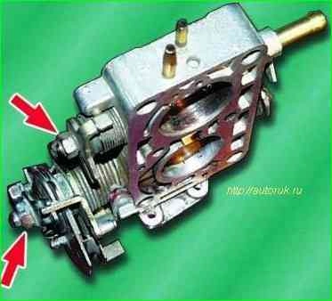
to disassemble the throttle valve drive mechanism, you need to unscrew the nuts securing the drive parts on the valve axles, having previously marked the location of the parts on the axes, and remove the parts
After disassembling, wash the carburetor parts in gasoline or solvent, then blow out all channels in the carburetor parts with compressed air.
Assembly and installation
Assembly unit of the carburetor and the carburetor itself as a whole, as well as its installation on the engine, is carried out in the reverse order of disassembly, taking into account the following:
- 1. It is necessary to check the mating surfaces of the throttle body for nicks and cracks.
- 2. Check the ease of rotation of the dampers in the housing and the clarity of their return to their original position after removing the force.
- 3. Check the mating surfaces of the carburetor body for nicks and warping in the area of the holes for the mounting screws.
- 4. All cardboard, paronite and rubber gaskets must be replaced with new ones.
- 5. The screws connecting the carburetor body parts should be tightened tightly, but without applying excessive force that could lead to deformation of parts made of soft alloys.
- 6. The nuts securing the carburetor to the engine intake pipe should be tightened without excessive force and only on a cold engine.
- 7. After assembly and installation, the carburetor must be adjusted
Adjustment
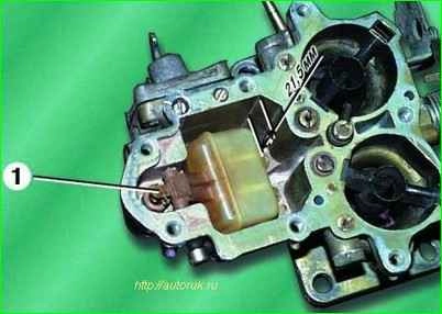
The fuel level in the float chamber is adjusted with the carburetor cover removed.
You can, without disconnecting the trigger rod, unscrew the screws securing the cover, lift it and, after removing the gasket, turn the cover to the side as far as the gaps in the places where the rod is attached will allow.
Pump gasoline into the float chamber using the manual pump lever until the level stabilizes
The distance from the fuel level to the upper plane of the carburetor body should be 21.5 mm
If the fuel level is below the specified level, it is necessary to bend up the float tongue 1, which rests against the shank of the shut-off valve needle
If the level is higher, bend the tongue down.
After each bending of the tongue, you need to unscrew the drain plug of the float chamber, drain the gasoline from it and, screwing the plug back into place, re-pump gasoline using the manual pump lever
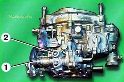
You can adjust the starting system directly on the car by completely warming up the engine and connecting a tachometer to it
Starting the engine with the air filter removed and lightly pressing the accelerator pedal, completely close the air damper with its drive handle
Then use the blade of a screwdriver to open the air damper as far as the lever mechanism will allow
The engine crankshaft rotation speed should be 2500-2700 min. If it differs from the specified one, you need to loosen the lock nut on the adjusting screw that rests on the profile lever and screw this screw in or out.
After completing the adjustment, tighten the locknut tightly.
Adjust the idle system on a warm engine with a tachometer connected to it.
To do this, with the engine running, set quality screw 2 to the position that ensures maximum idle speed.
Then, using quantity screw 1, set the frequency increased by 100-120 min. After this, tighten the quality screw until the rotation speed decreases by 100-120 min
This method of adjustment allows you to meet exhaust toxicity standards. It is recommended to make more precise adjustments using a gas analyzer.
Check
Check the operation of the accelerator pump with the carburetor cover removed after adjusting the fuel level
When the throttle valves are opened sharply, a strong, even stream of gasoline should emerge from the accelerator pump nozzle, reaching the channels of the throttle body without touching the walls of the diffusers
An uneven and curved jet indicates partial clogging of the sprayer channels
If there is no jet at all, make sure that the fuel supply screw of the nozzle and the injection valve located in it are clean and in good condition.
If they are in good working order, you should check the cleanliness and serviceability of the accelerator pump diaphragm mechanism by disassembling it as described above.
Checking the control unit and EPHH valve
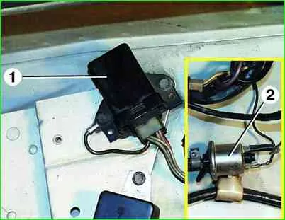
1. In addition to the above elements, the power system contains block 1 control EPHH and solenoid valve 2 installed in the engine compartment.
Together with an air valve and a microswitch installed on the carburetor, these devices form an EPH system that turns off the fuel supply in forced idling mode and prevents the engine from self-igniting after the ignition is turned off.
2. Both devices are of a non-separable design and must be replaced if they fail.
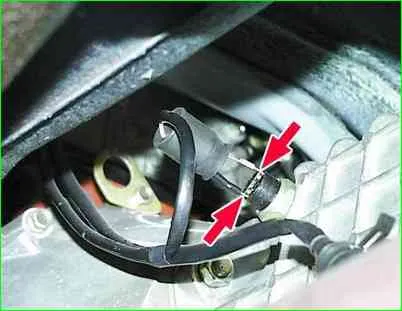
3. The serviceability of the solenoid valve is checked directly on the car.
To do this, remove any of the wires from the valve plug with the engine idling.
The engine should stop immediately
Continued engine operation with the carburetor systems and the EPHH pneumatic valve in good working order indicates a malfunction of the solenoid valve.
4. To check the serviceability of the EPHH control unit, connect a voltmeter to the wire connecting the solenoid valve to the control unit and to ground
At idle and at increased speed, the voltage at the solenoid valve plug must be at least 12 V.
Then, increasing the crankshaft speed to 2000-3000 min -1, you should sharply close the throttle valve. At the moment the throttle valve is closed and until the rotation speed is reduced to 1100 min, there should be no voltage on the solenoid valve plug.
If the voltage remains unchanged when the throttle valve is released, any wire should be disconnected from the microswitch of the carburetor EPH system.
If, at a crankshaft speed of more than 1600-1800 min -1, a voltage drop of 0.5 V or lower is recorded, there is a short circuit in the microswitch or its installation is incorrect.
If the voltage does not drop, the control unit is faulty. This malfunction is indirectly confirmed by the operation of the engine from self-ignition after the ignition is turned off.
Air filter
Replacing the air filter element
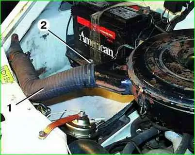
- 1. Remove hose 3 for crankcase ventilation. Disconnect the four spring clips 1 and remove the filter cover 2.
- 2. Remove the filter element.
- 3. Wipe the inside of the filter housing and cover. At the same time, make sure that dust and dirt do not get into the carburetor
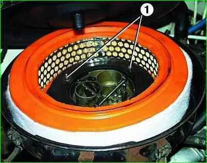
- 4. Install the new filter element into the filter housing, close the cover and fasten the spring clips. Install the crankcase ventilation hose.
Replacing and adjusting the draft of the carburetor air damper
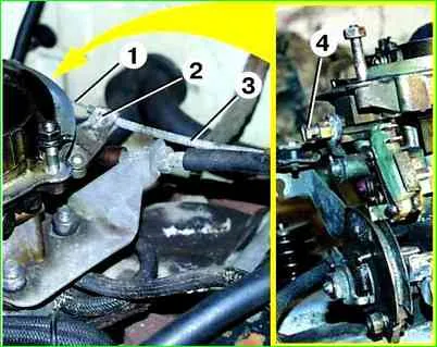
- 1. Unscrew screw 4 and remove rod 1 from the air damper drive lever. Unscrew screw 2 and remove shell 3 of the rod from the bracket on the carburetor.
- 2. Without removing the shell, pull the rod out of it by the handle into the car interior.
To replace the rod shell, you need to unscrew the nut on the bracket under the steering column and pull the rod shell into the passenger compartment.
- 3. Insert a new rod into the shell from the passenger compartment side and secure it with a screw to the air damper drive lever.
If the shell was removed, you must first install the rod shell from the passenger compartment side and secure it with a nut on the bracket, then insert the rod into it.
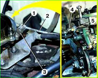
4. Adjust the air damper draft. to do this, press all the way on the traction control located under the steering column.
Loosen screw 4 and fully open the air damper by turning lever 5 of the damper drive. Then tighten screw 4.
Pull the thrust handle towards you until it stops; the air damper should close completely.
If this does not happen, loosen screw 1 and move the shell 2 of the rod in bracket 3 The air damper must be completely closed.
Check the opening and closing of the air damper again by moving the thrust handle from lock to lock.
Calibration data for carburetor K-151
Primary camera:
- Diffuser diameter 23 mm
- Mixing chamber diameter 32 mm
- Main fuel jet capacity 225 cm³/min
- Main air jet capacity 330 cm³/min
- Performance of idle fuel jet and transition system 95 cm³/min
- Performance of the first idle air jet and the transition system air jet 85 cm³/min
- Performance of emulsion jet idle 280
- Performance of the second idle air jet 330
- Flow of the accelerator pump for 10 full strokes 10±2.5 cm³/min
- Fuel level from the top plane of the body 21.5±1.5 mm
- The gap at the lower edge of the air damper after starting is 6±1 mm
Secondary camera:
- Diffuser diameter 26 mm
- Mixing chamber diameter 36 mm
- Main fuel jet capacity 380 cm³/min
- Main air jet capacity 330 cm³/min
- Performance of idle fuel jet and transition system 150 cm³/min
- Performance of the first idle air jet and the transition system air jet 270 cm³/min
- Flow of the accelerator pump for 10 full strokes 10±2.5 cm³/min
- Fuel level from the top plane of the body 21.5±1.5 mm


