Electromagnetic injector (0280150560B or ZMZ DEKA IA9Z61) – an electromechanical valve operating on the principle of an electromagnet
When voltage is applied to the injector winding, an electromagnetic field is created, which draws in the core along with the needle of the shut-off device and passes fuel to the spray holes.
An additional fuel filter is installed in the injector inlet channel.
Faults in which the injectors are checked:
- - difficulty starting the engine;
- - unstable engine operation;
- - idle speed reduced or increased;
- - jerks and failures in engine operation;
- - insufficient engine power;
- - glow ignition;
- - increased content of CO and CH.
Checking the injector without removing it from the engine
To check the serviceability of the injector, turn off the ignition and remove the negative terminal of the battery.
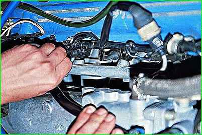
Use an awl or a thin screwdriver to snap off the spring clamp of the block
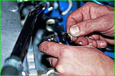
Disconnect the connector from the injector.
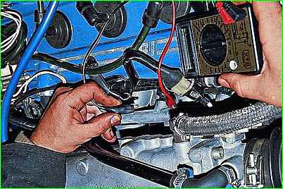
Connecting an ohmmeter to the injector terminals, measure the winding resistance
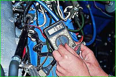
The winding of a working injector should have a resistance of 15–16 Ohms between the central and side pins of the connector
We carry out further tests on the injector removed from the engine.
Removing the injector
Relieve the fuel pressure in the power system. Turn off the ignition and remove the negative terminal of the battery.
Disconnect the idle air control connector.
Remove the air supply duct and the air damper drive cable from the throttle pipe (see "How to remove and install the throttle assembly of a Gazelle car").
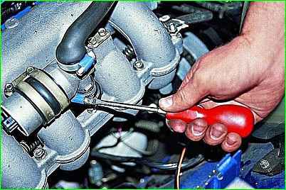
Use a screwdriver to loosen the clamp of the lower (outlet) hose of the idle air regulator.
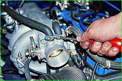
Use a screwdriver to loosen the clamp and remove the crankcase ventilation hose.
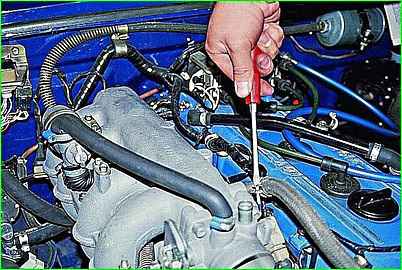
Use a screwdriver to loosen the clamp and remove the brake booster hose.
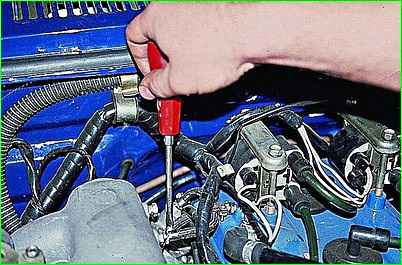
Use a screwdriver to loosen the clamp and remove the fuel pressure regulator hose.
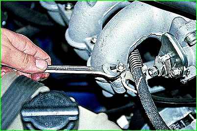
Using a 13mm wrench, unscrew the nut securing the tip of the ground wire to the first stud of the intake manifold.
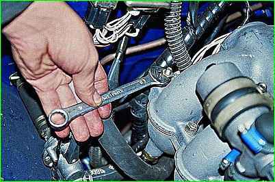
In the same way, disconnect the wire from the last stud of the intake manifold.
Then, unscrewing the remaining nuts of the intake manifold studs with a 13mm wrench, remove the receiver
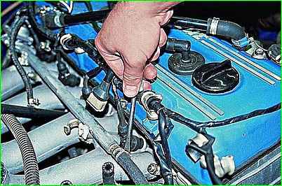
We loosen the clamp with a screwdriver
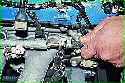
Remove the supply hose from the fuel rail fitting.
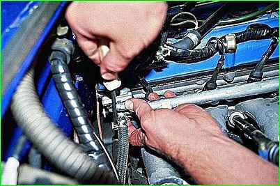
Use a screwdriver to loosen the clamp and remove the crankcase ventilation hose from the idle air system pipe.
Use a screwdriver to loosen the clamp and remove the drain hose from the fuel pressure regulator fitting.
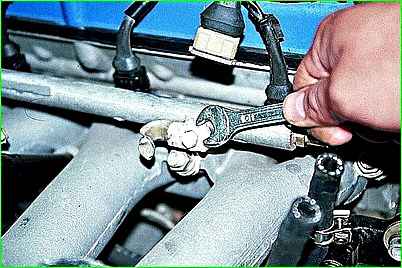
Using a 10mm wrench, unscrew the two screws securing the fuel rail to the intake manifold and remove the rail
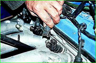
Pry the spring latch of the block with an awl and disconnect the connector from the injector
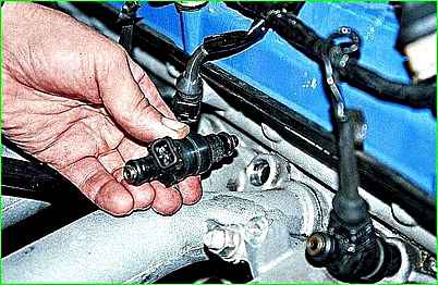
Remove the injector from the manifold.
Install the nozzle in reverse order.
Checking the injector removed from the engine
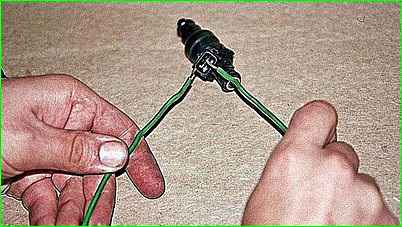
When voltage is applied briefly from the battery, a distinct click should be heard.
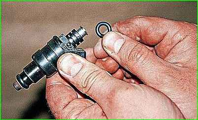
Remove the sealing collar from the nozzle flange and connect the nozzle with a rubber hose with a clamp to a source of compressed air (a compressor with a pressure gauge or a foot pump).
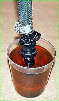
Having lowered the nozzle spray into kerosene, we supply air to it at a pressure of 3 kgf/cm 2
For a working nozzle, air should not pass through the nozzle.
We check the quality of atomization of the fuel injector, for which:
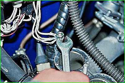
We connect the ground wires that were removed from the intake manifold studs when removing the injectors.
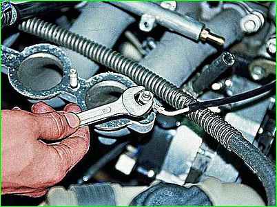
By tightening the nuts with a 13mm wrench, we ensure reliable contact with ground
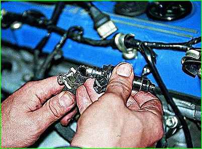
Place the fuel rail supply hose onto the injector flange and tighten the clamp with a screwdriver
Connect two wires at least 1 meter long to the injector terminals.
After making sure that the ignition is turned off, connect the negative terminal of the battery.
Turn on the ignition and, after waiting for the fuel pump to stop working, turn off the ignition.
Having secured the nozzle above the container, briefly connect the wires to the battery terminals.
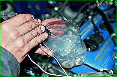
The injector should produce a conical spray of finely atomized fuel.
If the injector does not work, change the polarity of the wires.
Relieve the pressure in the fuel line by applying voltage to the injector.
Pour the gasoline into a suitable container
Replace the faulty injector.
Install all parts in reverse order.


