Disassembling the cylinder block was discussed in the article - "Disassembling the cylinder block"
After disassembling the cylinder block, it is necessary to determine the possibility of further use of the cylinder block, crankshaft and piston group
Checking the cylinder block
The non-flatness of the seating surface of the cylinder block is allowed to be no more than 0.03 mm. Grinding is not allowed.

The check must be carried out according to the diagram in Figure 1.
Determining the cylinder diameter

Distance X from the axis of the holes (1) to the seating surface of the cylinder block determines the group of cylinder diameters (see the table for details).
Mark (2) corresponds to cylinder No. 1, and mark (3) corresponds to cylinder No. 4 (see Fig. 2).
Table 1. Cylinder diameters
Position of holes, mm - Size group mark - Cylinder diameter mm:
- X=17 - A - From 79.500 to 79.510;
- X=27 - B - From 79.510 to 79.520;
- X=37 - C - From 79.520 to 79.530
Diameters of main bearing supports
The size of the diameters of the main bearing supports in the cylinder block is given in Table 2.
The size of the main bearing shells is given in Table 3.
Table 2. Diameters of the holes of the main bearing supports in the cylinder block
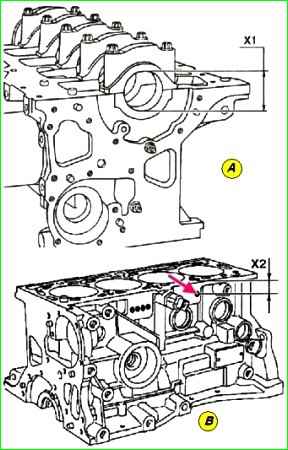
Position of holes 2 and 3, mm - Class mark - Diameter of the crankshaft supports X1, mm:
- X2=17 - 1 - From 51.936 to 51.942;
- X2=27 - 2 - From 51.942 to 51.949
Table 3. Main bearing shell sizes
First group by block hole diameter:
Size groups by main journal diameter and shell thickness, mm
- A or D Yellow mark C1=1.949—1.955;
- B or E Blue mark C1=1.946—1.952;
- C or F Black mark C1=1.943—1.949
Second group by block hole diameter
Size groups by main journal diameter and shell thickness, mm
- A or D Red mark C4=1.953—1.959;
- B or E Yellow mark C1=1.949—1.955;
- C or F Blue mark C2=1.946—1.952
Before checking, it is necessary to install the crankshaft main bearing caps, installing cap No. 1 from the flywheel side.

After tighten the crankshaft main bearing cap fastening bolts in the order shown in Figure 3.
Measure the diameters and remove the crankshaft main bearing caps.

The diameters (X1 Figure 4) of the crankshaft bearings are marked by drilling in the area above the oil filter (Fig. 4 (B) by the arrow).
The position (X2) of the holes in relation to the seating surface of the cylinder block determines the diameter of the crankshaft bearings.
The crankshaft lies in the cylinder block on five bearings. Thrust half rings, regulating the axial clearance, are installed on support No. 3.
Permissible parameters of the crankshaft:
Axial clearance of the crankshaft with new thrust half rings - 0.045 - 0.252 mm;
Axial clearance of the crankshaft with worn-in thrust half rings - 0.027 - 0.054 mm.
Diametric clearance between the main journals of the crankshaft and the bearings, mm - 0.027 - 0.054 mm.

Measuring the diameters of the crankshaft journals in Figure 5.
Table 4. Size groups by the diameter of the main journals
Group - Diameter of the main journals, mm:
- A/D - From 47.990 to 47.997;
- B/E - From 47.997 to 48.003;
- C/F - From 48.003 to 48.010
Table 5. Size groups by connecting rod journal diameter:
Group - X3, mm:
A - 43.960; B - 43.961; C - 43.962; D - 43.963; E - 43.964; F - 43.965; G - 43.966; H - 43.967;
J 43.968; K- 43.969L - 43.970; O - 43.971; P - 43.972; R - 43.973; S - 43.974; T - 43.975;
U -43.976; V -43.977; W - 43.978; Y - 43.979; Z - 43,980
When measuring, the minimum diameter along the journal perimeter is taken as the result.
Crankshaft marking

Location of factory marking and marking information in Figure 6.
The markings carry the following information:
- 1 — size groups by main journal diameter;
- 2 — size groups by main journal diameter No. 1 on the flywheel side;
- 3 — size groups by main journal diameter No. 5 on the flywheel side;
- 4 — size groups by connecting rod journal diameter;
- 5 — size groups by connecting rod journal diameter No. 1 on the flywheel side.


