The cylinder block is cast from aluminum alloy. Cylinder liners cast from wear-resistant cast iron are inserted into it
There are five main bearing supports at the bottom of the block.
The main bearing caps are made of ductile iron and are attached to the block with two studs.
The bearing caps are processed together with the block, so they cannot be swapped.
The first bearing cover is machined at the ends together with a block for installing two thrust washers to limit the axial movement of the crankshaft.
On the covers of the 2nd, 3rd and 4th bearings their serial numbers are stamped.
Attached to the front end of the block is a timing gear cover cast from aluminum alloy, into which the crankshaft seal is inserted.
The clutch housing is attached to the rear end of the block. The oil sump is attached to the bottom of the block, and the cylinder head is attached to the top.
The block head is cast from aluminum alloy. It has vertically mounted inlet and outlet valves.
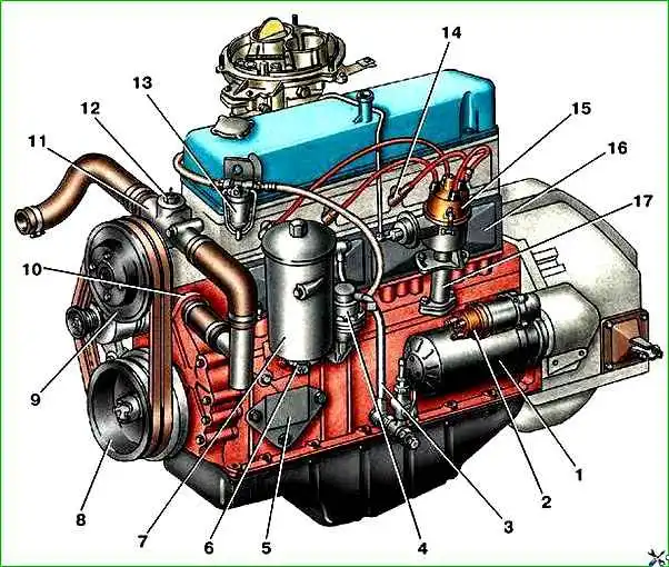
Type of engines mod. ZMZ-402 and ZMZ-4021 on the left side:
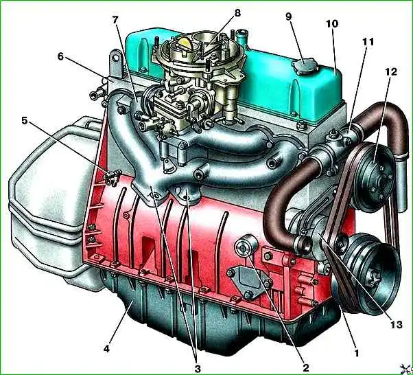
Type of engines mod. ZMZ-402 and ZMZ-4021 on the right side:
Cross-section of engines mod. ZMZ-402 and ZMZ-4021:
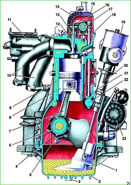
The general view and cross-section of the engines are shown in the figures.
The engines are in-line four-cylinder, equipped with carburetors and a contactless ignition system.
Both are similar in design, but the engine mod. 4021 deformed.
The valves are driven from the camshaft located in the cylinder block, through pushers, rods and rocker arms. The axis of the valve rocker arms is installed in the cylinder head on racks.
Valve seats and guides are installed in the cylinder head with high interference.
Combustion chambers are located in the lower part of the block head.
Engine block heads mod. 402 and 4021 differ in combustion chamber volume and height.
Height of engine block head mod. 402 is equal to 94.4 mm, mod. 4021 - 98 mm.
The top of the block head is closed with a cover stamped from sheet steel.
The pistons are cast from aluminum alloy, the piston bottom is flat.
For proper installation of the piston into the cylinder, the inscription “Front” is cast on the side wall of the boss under the piston pin: “Front.”
The piston is installed in the cylinder so that this inscription faces the front of the engine.
Each piston is equipped with two compression rings and one oil scraper ring.
The upper compression ring is cast from high-strength cast iron.
The working surface of this ring is coated with a layer of chrome to increase wear resistance.
The working surface of the lower compression ring, cast from gray cast iron, is coated with a layer of tin, which improves its running-in.
There is a groove on the inner surface of this ring. The ring should position this groove upward, towards the piston bottom.
The oil scraper ring consists of four elements: two steel discs and two expanders, axial and radial.
The working surface of the discs is covered with a layer of chrome.
The piston is attached to the connecting rod with a “floating” type piston pin, i.e. the pin is not secured in either the piston or connecting rod.
The pin is kept from moving by two spring retaining rings, which are installed in the grooves of the piston bosses.
Forged steel connecting rods, with an I-section rod. A tin bronze bushing is pressed into the upper head of the connecting rod.
The lower head of the connecting rod with a cover, which is secured with two bolts. The nuts of the connecting rod bolts are locked with Unigerm-9 sealant.
The connecting rod caps are processed together with the connecting rod, so they cannot be moved from one connecting rod to another.
Cylinder numbers are stamped on the connecting rods and connecting rod caps.
There is a hole in the connecting rod rod near the lower head for lubricating the cylinder mirror.
This hole should point to the right, away from the camshaft.
The mass of the pistons assembled with the connecting rod should not differ by more than 12 g for different cylinders.
Thin-walled connecting rod bearings are installed in the lower head of the connecting rod. The crankshaft is cast from high-strength cast iron.
The shaft is held against axial movement by thrust washers installed on the front journal.
At the rear end of the shaft there is a seat for installing a ball bearing for the gearbox input shaft.
A flywheel cast from gray cast iron is attached to the rear end of the crankshaft with four bolts.
")

")
")
")
")
")
")
")