K-151 carburetors, like any other carburetors, are devices for precise dosing of fuel in the air flow, formation of a combustible mixture from fuel and air and regulation of its supply to the engine cylinders
Carburetors have two side-by-side vertical channels for air passage, at the bottom of each of which a rotary throttle valve is installed.
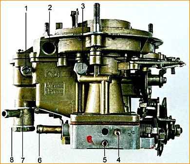
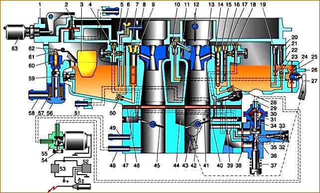
Fig1. Carburetor K-151: 1 – screw-plug of the float axis; 2 – tide for installing the electromagnet of the float chamber ventilation system (in K-151V carburetors); 3 – threaded plug of the fuel nozzle of the secondary chamber transition system; 4 – vacuum tap into the vacuum regulator of the ignition distributor; 5 – vacuum sampling fitting to the EPHH control valve; 6 – fitting for the crankcase ventilation system; 7 – boss with fuel fittings; 8 – boss fastening screw;
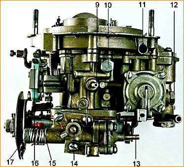
Fig. 2. Carburetor K-151: 9 – fitting for vacuum control of the exhaust gas recirculation valve; 10 – threaded plug of the emulsion jet of the idle system; 11 – boss for the float chamber ventilation fitting (only for K-151V); 12 – threaded plug for draining fuel from the float chamber; 13 – fitting for supplying vacuum to the EPHH valve; 14 – screw for adjusting the mixture composition at idle (the “quality” screw); 15 – screw-stop of the primary chamber damper lever; 16 – EPHH control microswitch; 17 – idle speed adjustment screw (quantity screw)
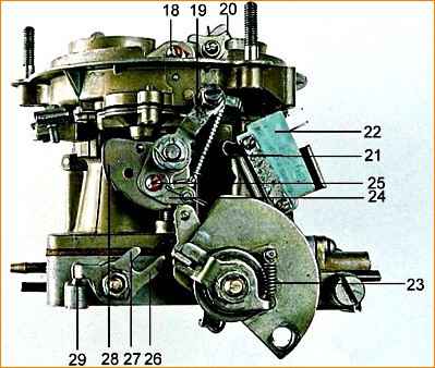
Fig. 3. Carburetor K-151: 18 – coupling screw of the halves of the double-arm starting lever; 19 – starting device control lever; 20 – lever on the air damper axis; 21 – air damper drive rod; 22 – microswitch of the EPHH system; 23 – freewheel tension spring of the throttle valve control lever; 24 – overhead lever of the starter control cam; 25 – adjusting screw for the position of the air damper drive rod; 26 – opening antenna of the throttle valve lever of the secondary chamber; 27 – closing antenna of the throttle valve of the secondary chamber; 28 – cam of the starting device; 29 – screw-stop of the secondary chamber damper lever
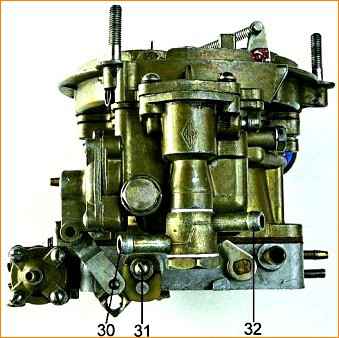
Fig. 4. Carburetor K-151: 30 – fuel outlet fitting; 31 – screw for fastening the accelerator pump cam (option); 32 – fuel supply fitting
Each of the channels is called a carburetor chamber.
Since there are two such channel-chambers, and the throttle valve drive is designed so that as you press the accelerator pedal, first one and then the other valve opens, carburetors of this type are called two-chamber with sequential opening of the chambers.
The chamber in which the throttle valve opens earlier is called primary, the other is called secondary.
In the middle part of each of the main air channels there are cone-shaped constrictions-diffusers, through which a vacuum is created in the air flow, necessary for sucking fuel from a special container located in the carburetor body - the float chamber.
The fuel level in the float chamber necessary for normal operation of the carburetor is maintained constant (more precisely, almost constant) using a mechanism with a float and a shut-off needle.
It should be noted that the float mechanism of the K-151 carburetor is fundamentally different from the similar device of all other domestic carburetors: it is completely, together with the needle and float, housed in the carburetor body and is accessible for visual inspection after removing the cover, without disturbing the natural interaction of the float with the level fuel.
The carburetor consists of three main parts:
- - top - housing cover, with a flange and studs for fastening the air filter, with a float chamber ventilation device and parts of the starting device, with seven screws for fastening to the carburetor body through a cardboard gasket;
- - middle - carburetor body, with a float chamber and float mechanism, fuel supply fitting and fuel metering systems;
- - lower - throttle body, with throttle valves and their drive mechanism, as well as with an idle device attached to the carburetor body from below with two screws through a composite gasket consisting of two thin - cardboard and one thick - plastic.
The carburetor contains the following systems, devices and mechanisms:
- - float mechanism;
- - fuel metering systems;
- - main dosing systems of the primary and secondary chambers;
- - idle system;
- - transition system of the secondary chamber;
- - econostat;
- - accelerator pump;
- - starting device;
- - economizer valve for shutting off fuel supply in forced idling mode (EFI);
- - forced crankcase ventilation system;
- - float chamber ventilation system;
- - throttle valve control mechanism.
The K-151, K-151D carburetor is installed on engines of the ZMZ-402 and ZMZ-4021 models.
The K-151 carburetor (Fig. 1) consists of three main detachable parts connected through sealing gaskets with screws.
The upper part - the carburetor cover includes an air pipe, divided into two channels, with an air damper in the channel of the first chamber.
The middle part consists of a float and two mixing chambers and is the carburetor body.
Bottom part - throttle body The nok includes mixing pipes with throttle valves of the first and second carburetor chambers.
The gasket between the middle and lower parts of the carburetor is sealing and heat-insulating.
Structurally, the carburetor consists of two mixing chambers - the first and second.
Each of the carburetor chambers has its own main metering system.
Idle system - with quantitative regulation of constant mixture composition (autonomous idle system).
In the second chamber of the carburetor there is a transition system with fuel supplied directly from the float chamber, which comes into operation when the throttle valve of the second chamber is opened.
The accelerator pump is diaphragm type. To enrich the combustible mixture at full load, an econostat is provided in the second chamber.
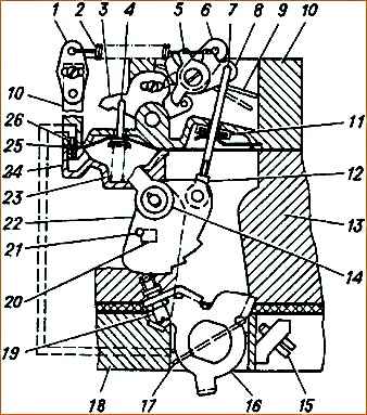
Diagram of a semi-automatic start-up and warm-up device: 1, 5, 6, 16 - levers; 2 - starting spring; 3 - intermediate lever; 4 - pneumatic corrector rod; 7 - traction; 8 - sector lever; 9 - air damper; 10 - carburetor cover; 11 - sealing element; 12 - adjusting coupling; 13 - float chamber body; 14 - air damper drive lever; 15 - thrust screw of the throttle valve of the primary section of the carburetor; 17 - throttle valve of the primary section of the carburetor; 18 - mixing chamber housing; 19 - screw with roller; 20 - emphasis; 21 - pin; 22 - profile lever; 23 - pneumatic corrector spring; 24 - pneumatic corrector cover
The cold engine starting system is a semi-automatic type, consisting of a pneumatic corrector, a lever system and an air damper, which is closed by the driver using a manual drive before starting a cold engine.
At the moment of starting the engine, the pneumatic corrector, using the vacuum that occurs under the carburetor, automatically opens the air damper to the required angle, ensuring stable operation of the engine when warming up.
When pulling out the choke lever, you must press the accelerator pedal.
The fuel supply cut-off system (forced idle economizer) comes into operation in forced idle mode when the vehicle is braking with the engine, when there is no need to supply fuel to the engine.
This ensures fuel savings and reduces the emission of toxic substances into the atmosphere.
The K-151 carburetor fuel shut-off system consists of a control unit, a microswitch for the solenoid valve and a forced idle economizer.
The microswitch and forced idle economizer are located on the carburetor, the solenoid valve - control unit - on the front panel of the cab.
The control unit is a device that, depending on the frequency of electrical pulses coming from the ignition coil, controls the solenoid valve.
When the accelerator pedal is released, the microswitch contacts should be open.
The fuel shut-off system works as follows.
When the accelerator pedal is released and the engine speed is more than 1400 rpm -1, the control unit does not supply voltage to the solenoid valve, as a result of which atmospheric air enters the forced idle economizer through the channels of the solenoid valve, the valve of which closes the idle channel.
In the event of a malfunction of the fuel shut-off system (the engine does not start or “stalls” when the throttle pedal is released), you must first make sure that the electrical contacts of the system elements are reliable, after which you should sequentially check the functionality of the solenoid valve, microswitch and control unit .
To check the solenoid valve and microswitch, you need to disconnect the electrical connector of the control unit, turn on the ignition (do not start the engine!) and from the engine compartment with one hand, smoothly open and close the carburetor throttle valves several times, and hold the solenoid valve with the other.
If the solenoid valve and fuse are working properly and if the microswitch is working properly and correctly adjusted, you should feel the activation of the solenoid valve (vibration, clicks).
To check the control unit, you need to insert the connector into the unit, turn on the ignition, start the engine and warm it up.
Then, from the engine compartment side, open the throttle valves approximately ⅓ of the stroke with one hand, and hold the solenoid valve with the other.
Release the throttle valves sharply.
In this case, if the control unit is corrected, the solenoid valve should turn off, and when the rotation speed decreases crankshaft until approximately 1050 rpm -1 the solenoid valve should turn on.
All carburetor systems are connected to a float chamber, the fuel level in which is maintained by float 2 and fuel valve 1 (see Fig. 1).
The main metering elements of carburetors are given in table. 1.
Calibration data for carburetor K-151
Diffuser diameter, mm:
- - primary chamber - 23;
- - secondary chamber – 26
Mixing chamber diameter, mm:
- - primary chamber - 32;
- - secondary chamber – 36
Performance of the main fuel jet, cm 3/min:
- - primary chamber - 225;
- - secondary camera – 380
Performance of the main air jet, cm 3/min:
- - primary chamber - 330;
- - secondary camera – 330
Performance of the idle fuel jet and transition system, cm 3/min:
- - primary chamber - 95;
- - secondary chamber – 150
Performance of the first idle air jet and the transition system air jet, cm 3/min:
- - primary chamber - 85;
- - secondary camera – 270
Idle speed emulsion jet capacity – 280
Performance of the second idle air jet – 330
Flow rate of the accelerator pump for 10 full strokes, cm 3/min - 10±2.5
Fuel level from the top plane of the body, mm - 21.5±1.5
Gap at the lower edge of the air damper after start-up, mm - 6±1
")

")
")
")
")
")
")
")