Adjusting the throttle and air damper drive of the carburetor
When the drive is adjusted correctly, it is necessary that the throttle and air damper open and close in accordance with the positions of the pedal and manual control buttons
Incomplete opening of the throttles leads to a decrease in engine power, and insufficient closing of the throttles causes increased engine crankshaft speed when idling and increased fuel consumption.
If the air damper does not open completely, then the combustible mixture becomes enriched, which causes excessive fuel consumption, and if it is not completely closed, starting a cold engine is difficult.
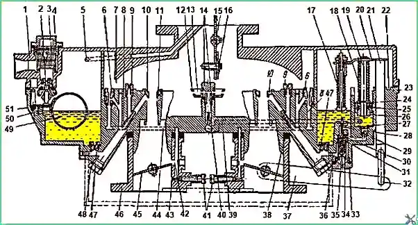
Fig. 1. K-88 carburetor: 1 - air damper housing; 2 - fuel supply needle valve; 3 - mesh filter; 4 - filter plug; 5 - channel for balancing the float chamber; 6 - idle jet; 7 - cutout; 8 - full power jet; 9 - air jet; 10 - small diffuser; 11 - annular gap; 12 - nozzle; 13 - air cavity; 14 - hollow screw; 15 - air damper; 16 - automatic valve; 17 - pusher; 18, 35 - springs; 19 - rod; 20 - bar; 21 - rod; 22 - annular groove; 23 - float chamber housing; 24 - cuff; 25 - cuff spring; 26 - rod bushing; 27 - hole; 28 - intermediate pusher; 29 - ball inlet valve; 30 - seat; 31 - ball valve; 32 - rod; 33, 48 - plugs; 34 - economizer valve with mechanical drive; 36, 39, 44 - fuel channels; 37 - lever; 38 - gasket; 40 - needle discharge valve; 41 - idle adjusting screws; 42 - rectangular hole; 43 - idle system hole; 45 - throttle; 46 - mixing chamber housing; 47 - main jet; 49 - float; 50 - float spring; 51 - float axis
First, adjust the foot and hand throttle drives, and then the air damper drive.
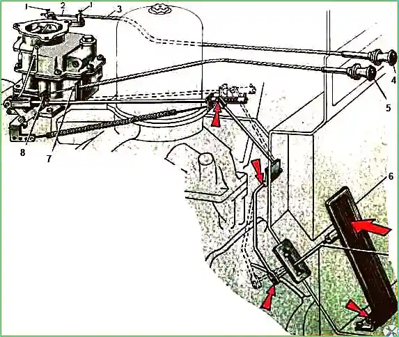
The foot drive is adjusted using the threaded fork on the carburetor rod and the threaded rod of the throttle pedal so that when the throttle is fully open, the pedal does not reach the floor by 3-5 mm
 .
.
Fig. 2. Adjusting the carburetor flap control drive: 1 - cable mounting screws; 2 - drive cable; 3 - cable casing; 4 - carburetor air flap drive button; 5 - throttle valve drive button; 6 - pedal rod; 7 - cable casing; 8 - bracket
The throttle pedal travel must be at least 160 mm.
After adjustment, the rods are secured with lock nuts.
The manual throttle drive is adjusted with a clamp, which is installed at the end of the drive cable so that when the drive handle is fully retracted, there is a gap of 2.0-3.0 mm between the clamp and the bracket secured to the rod.
This gap is necessary so that when the manual throttle control handle is retracted, the return spring ensures that the throttles are covered.
The throttles in the closed position must tightly cover the channels of the mixing chamber; between the channel wall and the edge of the throttles, a gap of no more than 0.05 mm is allowed.
When adjusting the air damper drive, the manual control handle must be set so that it does not reach the stop of the cabin shield by 2.0-3.0 mm.
In this position, with the air damper fully open, connect the drive cable to the damper lever and clamp it with a screw, then secure the cable sheath in another clamp.
In the closed position, i.e. with the handle fully extended, the air damper must completely cover the throat channel for air passage; between the channel wall and the edge of the damper, a gap of no more than 0.15 mm is allowed.
Adjusting low engine idle speed.
Idle speed adjustment should ensure stable engine operation at idle with the lowest fuel consumption.
Adjustment is carried out on a running engine, warmed up to a normal temperature (80-95°C) of the coolant, with normal clearances in the valves and between the spark plug electrodes and with the air damper fully open.
Figure 1 shows a diagram that can be used to trace the operation of the idle system of the K-88A carburetor and the carburetor adjustment process. The K-88 carburetor diagram is similar.
At low engine idle speed, the vacuum from the intake manifold is transmitted through opening 43 of the idle system and rectangular opening 42 to channel 44.
Under the action of the vacuum, fuel from the carburetor float chamber, passing through the main jet 47, is directed to the idle jet 6.
To obtain the required mixture composition, air is mixed with the fuel, entering through the cutout 7.
The resulting emulsion enters the mixing chamber through openings 43 and 42.
When exiting the openings, the emulsion mixes with the main air flow passing into the chamber through the gap formed by the edge of the throttle 45 and the wall of the mixing chamber.
When adjusting, it should be taken into account that the K-88A carburetor is a two-chamber carburetor and that the qualitative composition of the combustible mixture in each chamber is adjusted by its own adjusting screw 41, independently of the other chamber.
It should be remembered that when the adjusting screws are tightened, the mixture becomes leaner, and when they are loosened, it becomes richer.
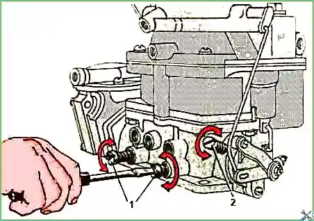
Fig. 3. Carburetor adjustment: 1 - mixture quality adjustment screws; 2 - throttle stop screw
In Fig. 4 shows the method for adjusting the K-88A carburetor on the ZIL-1Z0 vehicle.
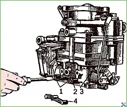
Fig. 4. Adjusting the idle system of the ZIL-130 carburetor: 1 - idle system adjustment screw; 2 - sealing housing; 3 - sealing cap
Before starting the engine and beginning adjustments, screw the idle speed adjustment screws 1 fully in, but not too tightly, and then unscrew each one by three turns.
After this, start the engine and perform quantitative adjustments, i.e. set the stop screw 2 to the smallest throttle opening at which the engine should run quite stably.
Then gradually tighten one of the screws 1 at each test by 1/4 turn until the engine starts running with obvious interruptions due to the large leanness of the mixture in the cylinders.
After this, enrich the mixture by unscrewing screw 1 by 1/2 turn.
Do the same with the second adjusting screw 1.
Having adjusted the mixture composition, you should try to reduce the idle speed by unscrewing gradually stop screw 2 of the throttles, and then try again to lean the mixture composition with both screws 1 in turn, as indicated above.
Usually after two attempts it is possible to find the correct position for all three adjusting screws and thus complete the qualitative and quantitative adjustment of the low idle speed of the engine.
To check the adjustment, press the throttle control pedal and immediately release it. If the engine stops, the idle speed should be increased.
With a properly adjusted carburetor, the engine should run steadily at 400-500 rpm of the crankshaft.
The method for adjusting the carburetor on the ZIL-1Z1 vehicle is the same as on the ZIL-130 vehicle.
Checking and adjusting the K-88 and K-88A carburetors can be performed on the simplest installations and using templates that can be made in a motor transport enterprise.
Checking the fuel level in the float chamber
The main reasons for an increased or decreased fuel level in the carburetor float chamber can be the following: a leaky float, its incorrect weight (normal weight is 18.7-19.8 g), jamming or leakage of valve 2 for fuel supply (Fig. 1).
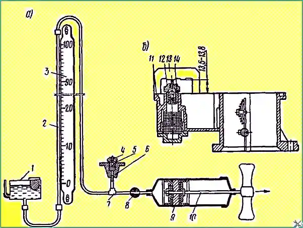
Fig. 5. Diagram of the vacuum unit and the needle valve assembly: a - checking the tightness of the needle valve assembly; b - checking the installation of the needle valve unit
One of the reasons for the increased or decreased fuel level in the float chamber may also be the incorrect installation of the fuel supply needle valve when assembling it on the carburetor air throat body.
Therefore, before proceeding with adjusting the fuel level, it is necessary to make sure that all units and parts included in the float mechanism are in good working order.
The tightness of the assembled fuel supply needle valve is checked on a vacuum unit (Fig. 5, a).
Needle valve unit 4 with gasket 5 is installed in housing 6, the tube of which is screwed into tee 7.
The operation of the unit is as follows
When valve 8 is open and piston 9 is moved by rod 10 in the direction indicated by the arrow, a vacuum is created in the cylinder vacuum, under the action of which the needle valve is pressed against its seat, and the water in the glass tube 2 rises upward.
Water level column is equal to the vacuum value in the cylinder.
The piston must be moved until the water in the glass tube reaches a height of 100 cm on scale 3 from the water level in tank 1, after which tap 8 should be closed.
If the needle valve is hermetically sealed, the water in the glass tube will not fall down; if there is no hermeticity, the water will fall down.
The permissible value of the drop in the water column in 0.5 min may not exceed 10 mm on scale 3.
To achieve hermeticity, grinding the needle valve to the seat is allowed.
If after this hermeticity is not achieved, the needle valve must be replaced with a new one.
When installing the needle valve unit 12 (Fig. 5, b) on the body 11 the air neck, it is necessary to correctly maintain the distance from the upper point of the needle valve sphere to the plane of the neck body.
This size is adjusted with gaskets 14, and it should be equal to 13.5-13.8 mm according to template 13.
The fuel level in the carburetor float chamber at a pressure in front of the needle valve within 125-170 mm Hg. should be 18-19 mm from the upper split plane of the float chamber body.
There are two ways to check the fuel level
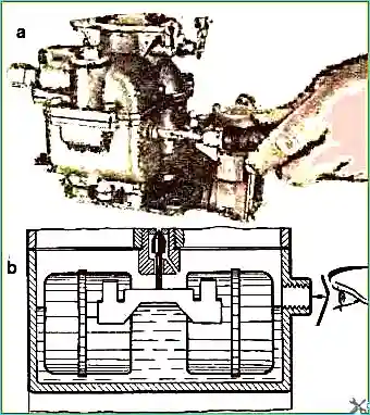
Fig. 6. How to check the fuel level in the carburetor with the engine running: a - unscrew the control plug; b - checking the fuel level
The first method is that when the engine is running at low idle speed, unscrew the inspection plug (Fig. 6, a) and observe the fuel level through the inspection hole located at eye level (Fig. 6, b).
When the level is adjusted correctly, the fuel will be visible, but it should not flow out of the hole.
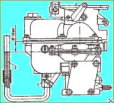
Fig. 7. Checking the fuel level in the carburetor removed from the engine
The second method of checking is to unscrew the plug closing the channel of the mechanical economizer valve and screw in adapter 1 (Fig. 7) in its place, ending with a glass tube 2 with marks on it indicating the limits of fuel level fluctuations in the float chamber.
The fuel level in the float chamber should be up to the upper or lower mark, i.e. at a distance of 18-19 mm from the split plane of the float chamber.
To obtain the correct fuel level in the float chamber (with the correct installation of the needle valve), it is permissible to bend the float bracket: at a high level, the float should be bent down, at a low level - up.
Checking the throughput of the carburetor metering elements
Maintenance of carburetor jets includes not only flushing and blowing out their calibrated holes, but also checking their flow capacity for outflow.
The efficiency of the carburetor, and therefore the engine, depends on the normal flow capacity of the jets, which is checked once a year.
The flow capacity of the jets is checked on two types of devices: for checking the jets for water outflow with an absolute determination of flow rate and for checking the jets with a relative measurement of water flow rate.
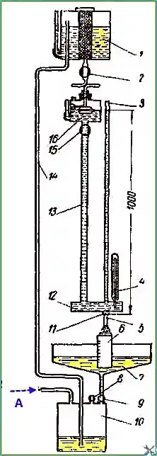
Fig. 8. Device for testing carburetor metering elements
Devices with absolute definition of jet capacity provide greater accuracy and stability of readings compared to devices with relative definition.
Therefore, it is better to use a device with absolute definition (Fig. 8).
The jet capacity is expressed in cubic centimeters of water flowing through the tested jet in 1 min, with a water column height of 1000 ± 2 mm (counting from the supporting surface of the jet) at a temperature of 20 ± 1 ° C, which is determined by thermometer 4.
When checking the capacity, the jets must be installed in the devices so that the liquid flows through them in the same direction as in the carburetor.
All jets must be cleaned of dirt before checking for leakage. burrs, dirt and oil, washed in clean gasoline and blown with compressed air.
During calibration, the dimensions of the jet holes are brought to the required size by gradually expanding them.
Chocking or soldering holes to reduce their throughput sti is not allowed.
If the diameter of the calibrated hole of the nozzle is larger than the norm, the nozzle must be replaced with a new one.
The dosing elements are checked in the following order.
Water from the upper tank 1 (see Fig. 8) through the tap 2 through the tube enters the float chamber 16, in which the float mechanism maintains a constant water level equal to 1000 mm from the supporting surface of the nozzle being checked.
From the float chamber, water through the tap 15 and tube 13 enters the body 12, rises through the glass tube 3 and simultaneously flows out through the nozzle being checked 5, screwed into the holder 11.
The water flowing out through the nozzle being checked enters the measuring cylinder 6 or tray 7, from where it flows through the tap 9 into the lower tank 10.
From the lower tank, as needed, water can be supplied to the upper tank 1 via pipe 14 using compressed air from a compressor or hand pump; taps 8 and 9 must be closed.
After filling the upper tank, first open tap 8, then tap 9 to avoid overflowing tray 7 with water.
To determine the jet capacity, place measuring cup 6 under the flowing stream of water and use a stopwatch to determine the time it takes to fill it with water.
The jet capacity is determined as the quotient of dividing the amount of water in the measuring cup in cubic centimeters by the time it takes to fill in minutes.
If the water flow stops exactly after 1 minute, then its volume in the measuring cup will indicate the jet capacity in cubic centimeters per minute.
For normal operation of the carburetor, it is also necessary to check the tightness of valve 34 (see Fig. 1) of the economizer with a mechanical drive; the check can be carried out on a vacuum unit (see Fig. 5, a) in the same way as the fuel supply needle valve is checked.
You should also visually check the fit of the ball 29 (see Fig. 1) and needle 40 valves of the accelerator pump to their seats, as well as their freedom of movement.
You should also check the correct operation of the moving mechanisms of the economizer valve with mechanical and pneumatic drives, the accelerator pump, the air damper 15 and the throttles 45, which must not hang or jam.
When checking the needle valve 40, you must unscrew the hollow screw 14 and remove the valve, remembering that the valve is not secured in its seat, and therefore can spontaneously fall out and get lost.


