K-22G vertical carburetor, with falling mixture flow, balanced
Consists of a float chamber, a main jet device, an additional (compensation) jet device, a starting device and an idle jet, an accelerator pump, a power jet (economizer), a mixing chamber and a limiter of the engine crankshaft speed.
Each jet consists of a plug with a calibrated hole (the jet itself), a spray tube and channels supplying gasoline from the float chamber to the jet and from the jet to the sprayer.
The sprayers of all the jets are brought out into the carburetor diffuser block.
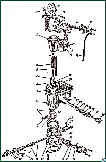
Fig. 1. Components of the K-22G carburetor: 1 - throttle valve; 2 - throttle valve needle bearing: 3 needle bearing roller mounting bushings; 4 - carburetor body; 5 - gasket; 6 - accelerator pump delivery valve; 7 - accelerator pump piston; 8 - piston rod; 9 - accelerator pump piston spring; 10 - diffuser block; 11 - accelerator pump spray nozzle; 12 - air damper; 18 - carburetor housing cover; 14 - choke shaft; 15 - choke drive lever; 16 - needle valve; 17 - float; 18 - drive rod; 19 - power jet; 20 - accelerator pump inlet valve; 21 - idle gasoline jet; 22 - sprayer block gasket; 23 - main and additional jet sprayer block; 24 - sprayer block gasket; 25 - main and additional jet block; 26 - gasket; 27 - main jet adjusting needle housing; 28 - needle seal; 29 - main jet adjusting needle and seal nut: 30 - accelerator pump drive lever rod; 31 - accelerator pump drive lever; 32 - throttle linkage bushings; 33 - idle speed adjusting screw; 34 - limiter coupling; 35 - spring; 36 - spring tension bushing; 37 - body
The carburetor consists of three main parts (Fig. 1): cover 13, body 4 and branch pipe.
A block of 10 diffusers is attached between the cover and the carburetor body.
A sealing gasket 5 is placed between the cover and the carburetor body for tightness. A sealing gasket is also placed between the carburetor body and the branch pipe.
At the bottom of the branch pipe there is a flange, which is used to attach the carburetor to the intake pipe with an iron-asbestos gasket on two studs.
Depending on the engine operating mode, gasoline for preparing the combustible mixture enters through various carburetor jets.
When starting a warm engine or when operating at low idle speed, gasoline enters the mixing chamber through the idle jet stroke.
At low and medium speeds in low and medium load modes, when the throttle valve is open more than at idle speed, but less than at full engine load, gasoline enters the mixing chamber only through the main jet.
As the engine speed increases, gasoline begins to flow through the additional jet.
And the higher the engine speed, the more gasoline passes through the additional jet.
The carburetor is designed and adjusted so that the engine always runs on a lean (economical) mixture in these modes.
When the engine develops the greatest power, the throttle valve is fully open.
In this case, not only the main and additional jets work, but also the power jet, through which an additional amount of gasoline passes, necessary to obtain a rich mixture.
The power jet is switched on every time fully or almost fully open the throttle at any engine speed, not just at the maximum.
The carburetor float chamber is located in front of the mixing chamber.
A constant fuel level in the float chamber is maintained by a float and a needle valve.
Gasoline from the gasoline pump enters the float chamber through a needle valve, which is closed by the float after filling the chamber to a normal level.
The fuel level in the float chamber is at a distance of 17-19 mm from the upper plane of the body.
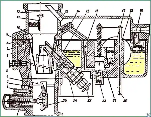
Fig. 2. Diagram of the K-22G carburetor: 1 - limiter spring; 2 - idle speed adjusting screw; 8 - increased speed spray hole; 4 - vacuum advance regulator drive tube hole; 5 - idle speed gasoline jet; 6 - elastic plate; 7 - emulsion jet; 8 and 9 - in Idle air jets; 10 - diffuser block; 11 - air damper valve; 12 - air damper; 13 - pressure balancing tube; 14 - accelerator pump nozzle; 15 - main and additional jet nozzle block; 16 - accelerator pump discharge valve; 17 - accelerator pump inlet valve; 18 - float; 19 - needle valve; 20 - accelerator pump rod; 21 - accelerator pump piston; 22 - power jet; 23 - main jet adjusting needle; 24 - main and additional jet block; 25 - throttle valve
The carburetor float chamber is balanced, i.e. the air space of the chamber is not connected to the outside atmospheric air, but to the carburetor cover pipe via tube 13 (Fig. 2).
The air pressure in the balanced float chamber is the same as in the carburetor housing cover pipe after the air filter.
The advantage of a balanced float chamber over an unbalanced one (connected to atmospheric air) is that the combustible mixture prepared by the carburetor is not enriched when the air filter is clogged.
When the engine is running, the air pressure in the housing cover pipe and, consequently, in the float chamber, is always less than atmospheric pressure.
This is due to the resistance of the air filter and the higher speed of air passing through branch pipe.
However, the air pressure in the diffusers is less than in the cover branch pipe, since the air velocity in the diffusers, which have a smaller flow area than the branch pipe, is always greater than the air velocity in the branch pipe.
Consequently, when the engine is running, the air pressure in the diffusers is always lower than in the float chamber.
To eliminate the possibility of outside air penetrating into the float chamber, causing a violation of its balance, since 1955 the carburetor cover has been attached to the body with seven bolts instead of five.
Main and additional jets
At the bottom of the carburetor body (Fig. 3) there is a socket through which the block 2 of the main and additional jets comes out into the diffuser block.
The block of jets is fixed in the socket by the block 5 of jets with sealing fiber gaskets.
Gasket 3 eliminates the possibility of gasoline penetration into the mixing chamber in addition to the sprayers, and gasket 4 ensures a tight connection of the channels of the main 14 additional jets with their sprayers.
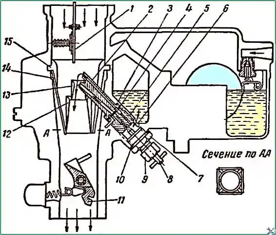
Fig. 3. Operation of the K-22G carburetor under medium loads: 1 - Air damper; 2 - sprayer unit; 3, 4 and 10 - gaskets; 5 - jet unit; 6 - channel; 7 - adjusting needle housing; 8 - main jet adjusting needle; 9 - seal nut; 11 - throttle valve; 12 - middle diffuser; 13 - small diffuser; 14 - elastic plate; 15 - neck of the diffuser block.
In the same socket with a sealing gasket 10, the housing 7 of the adjusting needle is screwed in, which is also the plug of the socket,
In the housing of the needle, an adjusting needle 8 is installed on the thread, which, when rotated, enters at different depths into the calibrated hole of the main jet, located in the center of the block 5, changing the cross-section of the jet. The needle is sealed with a gland located inside the nut 9.
There is a space between the needle body and the jet block, which communicates with the float chamber via channel 6, the additional jet is not located in the center of the jet block.
It communicates with its sprayer via an annular groove in the end of the jet block and in the end of the sprayer block.
When the engine is not running, the gasoline in the sprayers of the main and additional jets is at the same level as in the float chamber.
The sprayer block 2 is installed so that the sprayer of the main jet is in the smallest section of the small diffuser 13, and the sprayer of the additional jet is in the neck 15 of the diffuser block.
In Fig. 3 shows the operation of the carburetor at low speeds and low engine load, when the air damper 1 is fully open, and the throttle valve 11 is open more than at idle speed, but less than at maximum power.
In this case, all the air passes through the neck 15 of the diffuser block and then through two diffusers simultaneously: small 13 and medium 12, as well as through the gaps formed between the ends of the spring plates 14 of the diffuser block and the end of the medium diffuser (see section along A-A).
The air speed in the neck of the diffuser block is insufficient to create the pressure drop necessary for the operation of the additional jet, and in the small diffuser the air speed is sufficient to create the necessary difference in air pressure at the holes of the sprayer of the main jet and in the float chamber, causing gasoline to flow out of the sprayer.
For the main jet to operate, the pressure difference may be less than that required for the additional jet, whose sprayer end is higher than the sprayer end of the main jet.
In the small diffuser, gasoline is atomized by air for the first time. When leaving the small diffuser, it is atomized a second time (by the air that enters the middle diffuser).
When leaving the middle diffuser, gasoline is atomized again (by the air that passes through the gaps between the ends of the spring plates and the end of the middle diffuser).
As the engine speed increases, the air speed in the neck of the diffuser block and in the small diffuser increases.
This leads to an increase in the flow of gasoline from the sprayer of the main jet and the mixture leaving the middle diffuser becomes richer.
But, since with increasing air speed the spring plates of the diffuser block automatically move apart, letting air through, the composition of the mixture remains the same.
With a further increase in the opening of the throttle valve, the air speed in the neck of the diffuser block increases, causing gasoline to flow through the additional jet.
However, in this case, the composition of the combustible mixture remains the same as when one main jet is operating, since the throughput of the additional jet and the elasticity of the diffuser block plates are selected accordingly.
Accelerator pump
When the throttle valve is opened sharply, the combustible mixture becomes leaner.
This is because the rate of gasoline outflow increases much more slowly, 600 times less than the specific gravity of gasoline.
To ensure good responsiveness of the car, it is necessary that when the throttle valve is opened sharply, throttle valve, the combustible mixture is not depleted, but enriched.
When the throttle valve is opened sharply, the mixture is enriched with the help of an accelerator pump.
The accelerator pump consists of a well in which the piston moves, and a system of valves.
The piston is moved by rod 8, which, by means of rod 30 (Fig. 1) and lever 31 is driven by throttle lever 40.
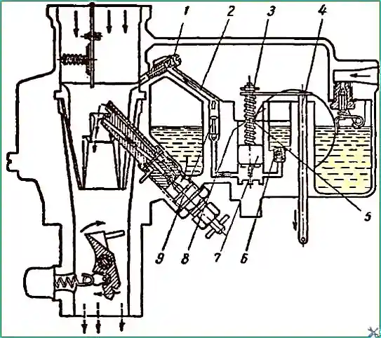
Fig. 4. Operation of the K-22G carburetor accelerator pump: 1 - accelerator pump nozzle; 2 - channel; 3 - piston rod; 4 - piston rod; 5 - spring; 6 - inlet valve; 7 - piston, 8 - bypass slot; 9 - accelerator pump discharge valve
In Fig. 4 shows the operation of the accelerator pump.
Gasoline flows from the float chamber into the pump well through the inlet valve 6, filling the well to the level of gasoline in the float chamber.
When piston 7 moves from top to bottom, gasoline pressure is created in the well, under the action of which inlet valve 6 closes and discharge valve 9 opens.
Gasoline passes through the discharge valve along channel 2 and is injected into the diffuser block through sprayer 1.
When the throttle valve is opened sharply, piston rod 4 moves along piston rod 3 and compresses piston drive spring 5.
When released, the spring moves the piston and ensures smooth and uniform fuel injection.
Thanks to this, fuel injection continues much longer than the opening period throttle valve.
When the throttle valve opens slowly, and, consequently, when the piston of the accelerator pump moves slowly, fuel injection does not occur, since the gasoline displaced by the piston goes back into the float chamber through the inlet valve 6, which does not close due to the lack of gasoline pressure.
For the same reason, the discharge valve 9 does not open, preventing gasoline from penetrating the diffuser block and enriching the mixture unnecessarily.
But already at an increased speed of opening the throttle valve, the gasoline pressure becomes sufficient to close the inlet valve, opening the discharge valve and injecting gasoline.
The gasoline that has penetrated the gaps and ended up on top of the piston, flows into the float chamber through the slot 8 during the piston's upward stroke.
In the carburetor The K-22G does not provide the ability to change the amount of gasoline injected by the pump depending on the season, since the accelerator pump capacity of 1.0 cm³ per working stroke ensures proper enrichment of the mixture for the winter season as well.
Power jet
It was already mentioned above that the engine develops its greatest power with a rich mixture.
When the car is running, the maximum engine power is used quite rarely.
To reduce the car's fuel consumption, the carburetor adjustment is selected so that at average loads In trucks, the engine runs only on an economic mixture.
The carburetor has a power jet that enriches the mixture when it is necessary to obtain the greatest engine power.
Figure 5 shows the design of the power jet.
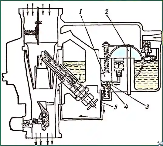
Fig. 5. Operation of the K-22G carburetor at maximum engine power: 1 - piston; 2 - piston rod; 3 - piston needle; 4 - power jet valve; 5 - power jet channel
The K-22G carburetor has a mechanical drive for switching on the power jet, which is combined with the accelerator pump drive.
The power jet consists of a ball valve 4, located at the bottom of the accelerator pump well, and a channel 5, through which fuel from the valve is supplied to the sprayer of the additional jet.
The drive rod of the accelerator pump piston is pivotally connected to the throttle valve so that when the throttle valve is closed, the piston is in the upper position, and when open, in the lower position.
Until the throttle valve is fully open, switching on the power jet is impossible.
To obtain the greatest power, the throttle valve is fully opened, the piston drops to the lower position and needle 3 presses on the ball of the jet valve and enriches the mixture.
Starter and idle jet
When starting a cold engine, the air flow through the carburetor is low and the mixture is not heated.
This does not allow all the gasoline to evaporate, and the starting fractions are mainly involved in the formation of the combustible mixture.
In order for the resulting combustible mixture to be able to start the engine under the specified conditions, several times more gasoline is required than under normal operating conditions; the mixture must be over-enriched.
Over-enrichment of the mixture is achieved by increasing the vacuum in the mixing chamber, as a result of which gasoline enters the mixing chamber not only from the idle jet, but also from the main and additional jets.
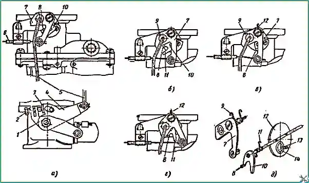
Fig. 6. Operation of the starting device of the K-22G carburetor: 1 - throttle lever; 2 - throttle lever adjusting screw; 3 - shoulder; 4 - lever with shoulder; 5 - lever drive rod with shoulder; 6 - flexible rod; 7 - air damper drive lever; 8 - air damper lever shoulder; 9 - drive lever spring; 10 - air damper lever; 11 - air damper lever spring; 12 - air damper; 13 - damper valve spring; 14 - damper valve
To re-enrich the mixture, the carburetor has a special device, shown in Fig. 6.
The device consists of an air damper 12 located in the upper part of the inlet pipe of the carburetor cover, two levers 7 and 10 and a flexible rod 6 of the damper drive.
In the pipe, the damper is attached to the axis not in the center, but so that its lower part is significantly larger than the upper one.
Two holes are stamped in the lower part of the damper, closed by valve 14 under the action of spring 13.
A lever 10 is fixed on the damper axis, which, by the force of spring 11, constantly holds the damper in the closed position.
The air damper is controlled from the dashboard by means of a flexible rod, the handle of which is located on the instrument panel.
The rod sets in motion the lever 7 of the drive, which has the shape of a fork, which, acting on the lever 10 of the air damper, by means of the bent shoulder 8 opens or closes the damper.
Spring 9 presses lever 7 to the position corresponding to the fully open air damper, and in case of sudden disconnection of the flexible rod holds the damper in the open position.
Fig. 6 shows the positions of the damper drive corresponding to:
- a) a forcibly closed damper; in this position of lever 7, the control handle of the flexible rod of the air damper drive is pulled out to the full extent of its travel;
- b) and c) the position of lever 7, which allows lever 10 (under the action of spring 11) to automatically close the damper or (Fig. 6, c) to automatically open the damper as much as the flow of air entering the branch pipe can open it, overcoming the action of spring 11; in this position of the lever 7, the flexible rod control handle is pulled out approximately ⅔ of its travel;
- d) the damper is forcibly fully open; in this position of the lever 7, the damper cannot close, since the lever 10 rests with its shoulder 8 against the lever 7; in this case, the flexible rod control handle of the damper drive is pushed into the guide sleeve completely by the value of its travel.
Carburetor operation The operation of the K-22G carburetor when starting a cold engine is shown in Fig. 7. Air enters through valve 3 of the closed air damper 2.
Narrow gaps remain between the throttle valve 5 and the branch pipe when starting the engine.
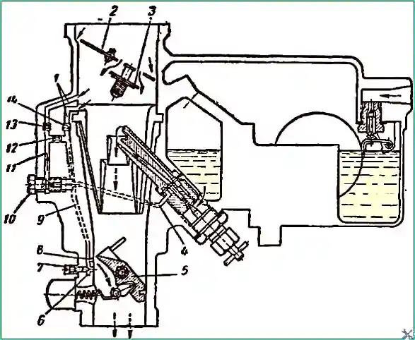
Fig. 7. Operation of the K-22G carburetor when starting a cold engine: 1 - air ducts; 2 - air damper; 3 - air damper valve; 4 - gasoline channel; 5 - throttle valve; 6 - low-speed spray hole; 7 - idle speed adjusting screw; 8 - high-speed spray hole; 9 - emulsion channel; 10 - idle jet; 11 - channel; 12 - emulsion jet; 13, 14 - air jets
Below the upper edge of the valve, in the area of the upper gap, in the branch pipe there are two spray holes 6 and 8, through which the emulsion prepared by the idle jet passes.
Both holes communicate with channel 9 in the carburetor body.
This channel connects holes 6 and 8 with the air jet 14 and the emulsion jet 12.
Channel 4 is connected to the socket of the gasoline jet 10, through which gasoline flows from the additional jet.
The gasoline jet is connected by channel 11 to the emulsion jet 12 and the air jet 13.
When the engine is not running, the gasoline in channel 11 is at the same level as and in the float chamber.
Under the action of the vacuum in the area of the spray holes, which occurs when the engine is started, gasoline from the float chamber through the gasoline jet 10 goes into channel 11.
Air from the carburetor cover pipe passes through channel 1 into the same channel through the air jet 13 and is mixed with gasoline for the first time.
The resulting emulsion goes through the jet 12 into channel 9, is mixed a second time with air, which is supplied to channel 9 through the air jet 14 and goes through channel 9 to the spray holes.
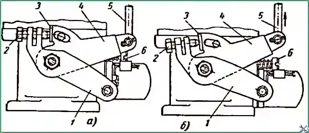
Fig. 8. Action of the lever with the shoulder when starting a cold engine: a - with the air damper open; b - with the air damper closed; 1 - throttle lever; 2 - throttle lever adjusting screw; 3 - shoulder; 4 - lever with shoulder; 5 - lever drive rod with shoulder; 6 - idle speed adjusting screw
The main atomization of gasoline occurs when the emulsion comes out of the spray holes 6 and 8 of the idle jet.
When the engine is started, the emulsion comes out of both holes.
The atomization of gasoline coming out of the sprayers of the main and additional jets occurs when the mixture passes through the gap between the throttle valve and the branch pipe.
Therefore, when starting a cold engine, the mixture valve does not need to be opened more than it opens automatically by shoulder 3 of lever 4 (Fig. 8) when closing the air damper.
If the throttle valve is opened more, then poorly atomized gasoline will throw the spark plugs, starting the engine will be impossible.
For starting a warm engine, as well as for engine idling a less rich mixture is required (about 9 parts by weight of air to one part of gasoline).
As a result, there is no need to close the air damper.
In this case, gasoline flows only through the idle jet.
The composition of the mixture prepared by the idle device depends on the throughput of the gasoline and air jets.
Adjusting screw 7 (see Fig. 6), installed opposite the lower spray hole 6, regulates only the amount of emulsion coming from the lower spray hole at low idle speed.
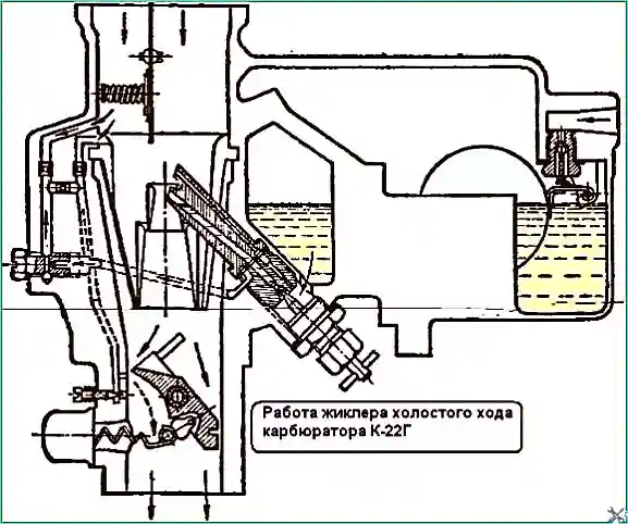
Fig. 9. Operation of the idle jet of the K-22G carburetor
The operation of the idle jet when starting a warm engine and at minimum idle speed of the engine is shown in Fig. 9.
The upper edge of the valve is located above the upper hole.
The emulsion comes from both holes.
The emulsion passes through the upper hole at increased idle speeds, and it serves for a smooth transition from engine operation at idle speeds to operation at medium loads.
Speed limiter
The speed limiter does not allow the engine crankshaft to develop speeds greater than necessary for normal operation of the truck mobile.
It operates automatically depending on the flow rate of the mixture in the carburetor.
The limiter, part of which is the throttle valve of the carburetor, reduces the filling of the cylinders with the mixture when the engine speed becomes greater than necessary for the movement of a loaded car at a speed of 70 km / h (in fourth gear, on a level section of the road), and also does not allow the crankshaft of the engine to develop without load more than 4300 rpm, which significantly extends its service life.
The limiter does not worsen the throttle response of the engine, since it does not prevent the engine from running with the throttle valve fully open until the crankshaft of the engine develops the maximum permissible speed.
The limiter is especially important in that it prevents the engine from "running away" when running without load.
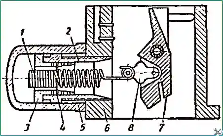
Fig. 10. Speed limiter: 1 - speed limiter spring; 2 - spring tension sleeve; 3 - speed limiter sleeve; 4 - spring mounting stud; 5 - cap, 6 - carburetor pipe; 7 - throttle valve; 8 - throttle valve earring
The speed limiter is shown in Fig. 10.
The limiter consists of a throttle valve 7, a spring 1, a sleeve 2 for tensioning the limiter spring and a coupling 3 of the limiter.
The carburetor throttle valve has a special shape and is located on an axis offset from the axis of the branch pipe.
The throttle valve drive has a special device.
In Fig. 1 clearly shows the device of the limiter and the drive of the damper.
The damper 1 is loosely mounted on the axis 38 on the needle bearing 2.
One end of the spring 35 is attached to the clutch 34 of the limiter by a pin that passes between the turns of the spring, and the other end is attached to the roller of the damper earring.
When the clutch 34 rotates, the number of working turns of the spring 35 changes.
The tension of the spring is adjusted by the sleeve 36, moving along the thread in the carburetor pipe.
To rotate the throttle valve, there are cams on its axis, into the groove between which the damper enters.
The thickness of the damper is less than the width of the groove between the cams, therefore there is a free stroke.
The free stroke is greater than the stroke of the valve before it is fully opened.
The position corresponding to the fully open valve is fixed by a pin pressed into the valve, which, when the valve is fully opened, rests against the carburetor pipe.
The limiter spring constantly strives to open the throttle valve, but the valve rests against the cams of the axis 38 (Fig. 1) and does not open until the driver presses the throttle pedal, turning the throttle shaft and thereby retracting the cams.
When the pedal is released, the throttle actuator pull-back spring turns the throttle shaft, the cams of the shaft press on the throttle, which closes, stretching the limiter spring.
As the engine crankshaft speed increases, the pressure of the mixture flow on the inclined surface of the throttle valve increases.
At the moment when the pressure of the mixture flow on the valve is stronger than the action of the spring, the valve begins to close regardless of the position of the pedal (which allows it to move freely in the groove between the cams), and the engine crankshaft speed decreases.
There is a special protrusion on the throttle valve earring.
It serves to increase the leverage of force application springs after the valve closes so much that it rests against this protrusion.
With further closing of the valve, the action of the limiter spring increases significantly and prevents the possibility of complete closing of the throttle valve under the action of vacuum and mixture flow.
The moment of entry of the limiter into action depends on the tension of its spring.
The tighter the spring, the higher the maximum engine crankshaft speed, since a greater pressure of the mixture flow is required to start closing the valve.
By changing the spring tension, it is possible to regulate the value of the maximum engine crankshaft speed.
The spring tension is controlled by two valve positions. One position corresponds to 3500 - 4300 rpm of the engine crankshaft when it is running without load.
In the K-22G carburetor, in this position, the valve is at an angle of 21 ÷ 23° relative to the position occupied by a fully open valve.
The valve is relatively little open, so the limiter spring is almost completely stretched, the other position corresponds to 2800-3175 rpm of the engine crankshaft with full load; in the K-22G carburetor, it corresponds to an angle of 3 - 4°, i.e. the valve is almost completely open.
The limiter spring is almost not stretched.
The spring tension mechanism is closed is dug with a cap, inside of which there are planes for locking the hexagons of the coupling and the spring tension nut, which eliminates the possibility of arbitrary changes in the adjustment.
The spring tension is adjusted at the factory using a special device, after which the screws for fastening the cap are sealed so that this adjustment cannot be disturbed during operation.


