External signs of the need to remove bearings for defect detection are:
- – increased noise when the wheel rotates;
- – inability to achieve the nominal clearance in the bearings by adjustment.
You will need: a key for wheel nuts, a hammer, a screwdriver, keys "13", "17", a torque wrench, a punch (punch), a mandrel for pressing in the oil seal, kerosene, Litol-24 grease, a container for washing parts.
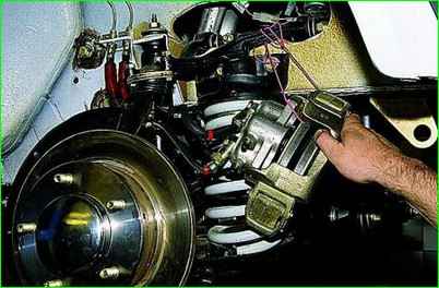
Disconnect the caliper from the pad guide and tie them with wire to the upper arm.
Unscrew the adjusting nut of the hub bearings.
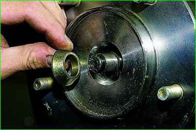
Remove the conical bushing.
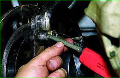
Use a chisel to bend the edge of the locking plate of the nut of the front fastening of the arm to the steering knuckle.
Similarly, we unlock the nut of the rear fastening.
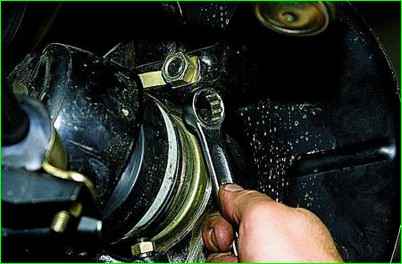
Using a 19 mm open-end wrench, unscrew the rear mount nut of the arm to the steering knuckle.
In the same way, unscrew the front mount nut.
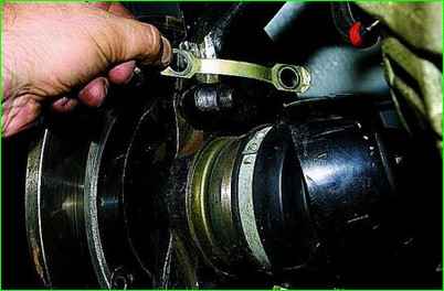
Remove the locking plate.
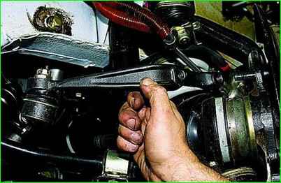
After removing the lever from the bolts, we move it away from the steering knuckle.
We disconnect the brake hoses from the steering knuckle.
We disconnect the upper and lower ball joints from the levers
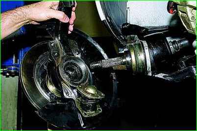
From the splines of the outer joint housing of the front wheel drive, remove the steering knuckle assembly with ball joints, hub unit and brake disc.
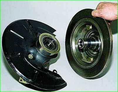
Disconnect the steering knuckle and hub with the brake disc.
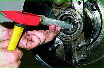
If you have difficulty separating the parts, clamp the steering knuckle in a vice and knock out the hub with a soft metal punch
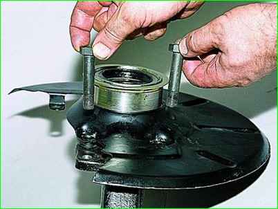
Now you can remove the mounting bolts lever to the steering knuckle
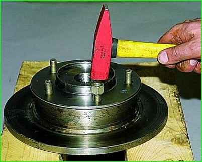
To disconnect the hub and the brake disc, screw the nut onto the stud and knock out the stud.
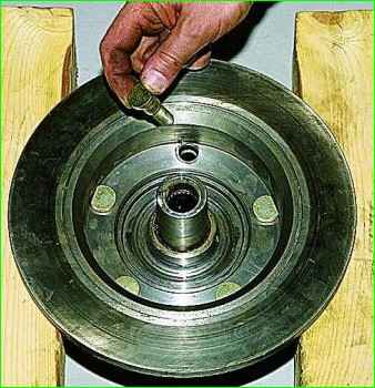
After unscrewing the nut, we take out the stud. Similarly, we dismantle the other studs
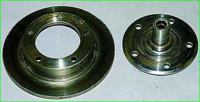
Disconnect the hub and brake disc.
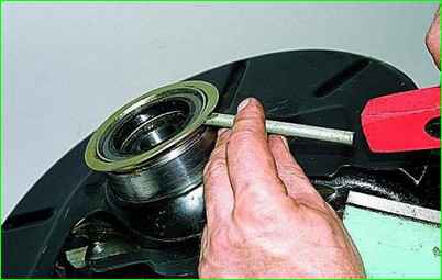
Use a chisel to knock off the mudguard ring.
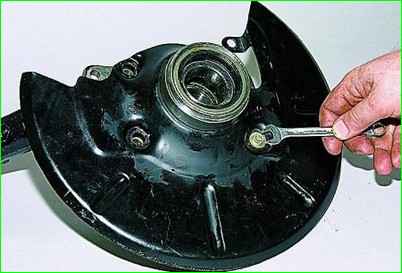
Using a 10 mm spanner, unscrew the protective cover mounting bolt
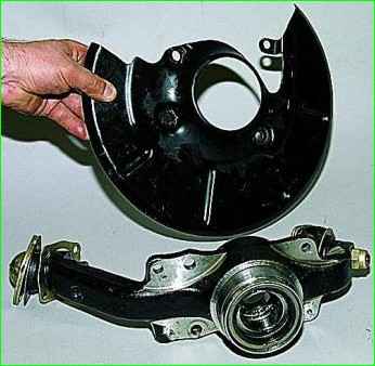
Remove the cover
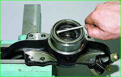
To remove the seals and hub bearings, clamp the steering knuckle in a vice.
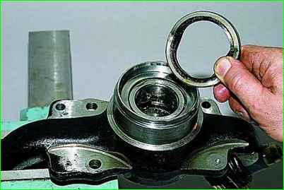
We pry the seal with a screwdriver and take it out.
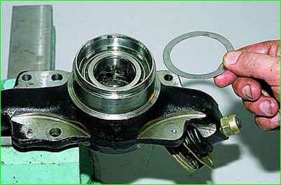
We take out the ring.
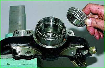
We take out the inner ring of the outer bearing with a separator and rollers.
We similarly take out the oil seal, ring and inner ring of the other (inner) bearing with a separator and rollers
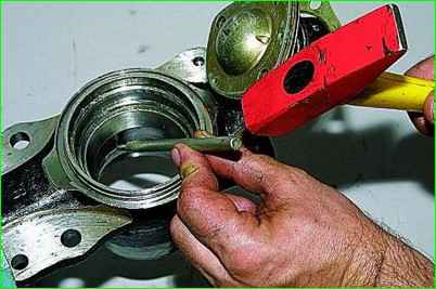
We knock out the outer ring of the outer bearing with a punch and take it out.
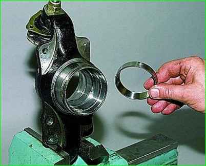
Similarly, knock out the outer ring of the inner bearing.
Assemble in the reverse order.
Before installing the bearings, clean the inner cavity of the steering knuckle from old grease.
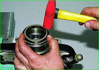
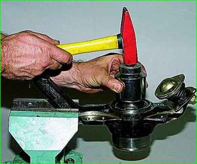
Using a suitable piece of pipe, press in the outer rings of the bearings.
Put 40 g of Litol-24 grease into the cavity of the steering knuckle and into the bearing separators.
Using a suitable piece of pipe, press in the seals.
Use the following mandrels: outer rings of the corresponding replaced (old) bearings.
It is more convenient to press in the rings using a press.
Insufficient pressing or skewing of the ring is not allowed.
Check the reliability of the fit of the rings in the hub housing.
The rings should not turn under the force of your hand.
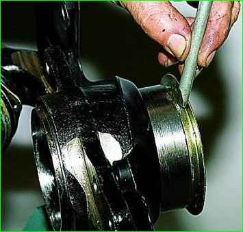
After installing the mudguard ring, use a chisel to press the metal of the ring into the groove of the swivel bearing in several places. fist.
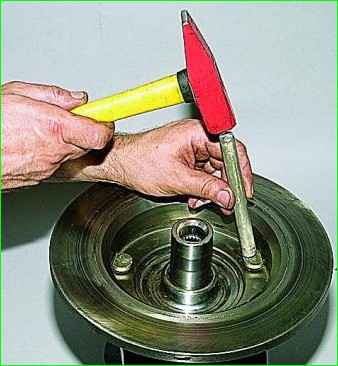
Having connected the brake disc to the hub, we press in the studs with a soft metal punch.
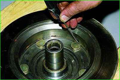
The heads of the studs with the milled surface must face the cylindrical surface of the brake disc.
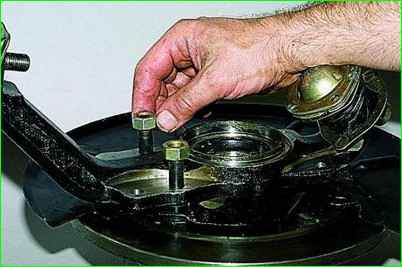
To prevent the bolts that secure the arm to the steering knuckle from falling out when installing it on the car, screw nuts onto them.
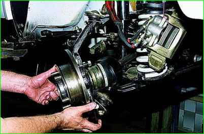
After inserting the tail of the outer joint of the drive into the splines of the hub, mount the steering knuckle.
After completing the assembly, adjust the clearance in the bearings (see Adjusting the hub bearings of the Niva Chevrolet).


