You will need: 8 mm and 10 mm wrenches, Phillips and flat-head screwdrivers, pliers for removing retaining rings
Remove the starter from the car (see "Removing and checking the starter of the VAZ-2123").
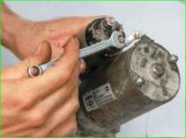
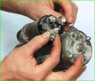
Unscrew the nut and disconnect the terminal of the wire of the "positive" brushes from the contact bolt
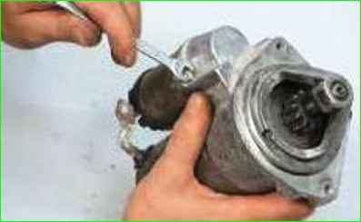
Unscrew the two bolts securing the traction relay and remove the relay.
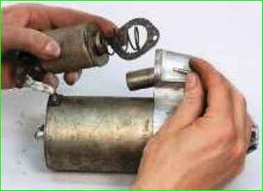
Pay attention to the gasket, do not forget to install it during assembly
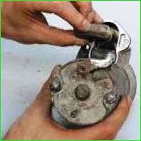
Remove the anchor of the traction relay by lifting it up so that the anchor loop is removed from the lever.
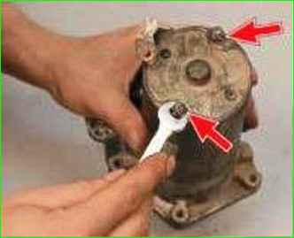
Unscrew the two nuts of the tie rods.
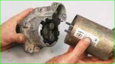
Remove the cover from the drive side with the gearbox and drive assembly
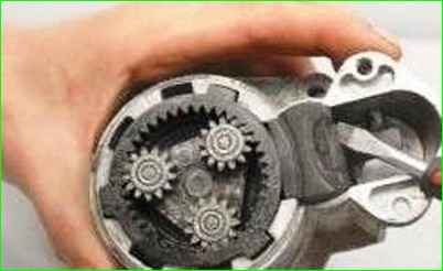
Use a screwdriver to pry the gearbox with the drive out of the cover.
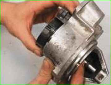
Remove the seal from the drive lever.
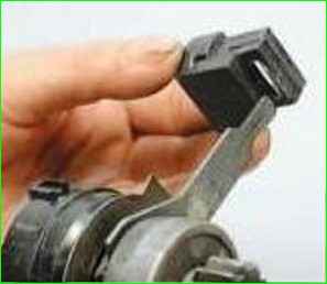
Replace a damaged or badly worn seal.
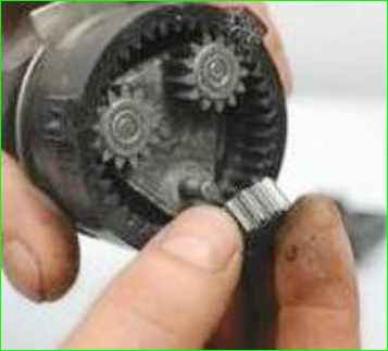
Remove the three planetary gears of the reduction gear from the carrier axles.
Inspect the gears, replace the gears if their teeth are damaged.
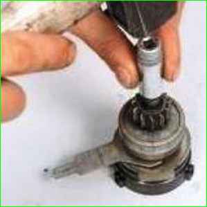
Knock the limiting ring off the retaining ring using a suitable mandrel
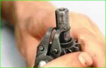
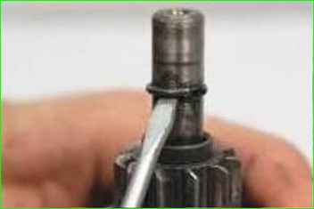
Using special pliers or by prying with a screwdriver, remove the retaining ring, and then the limiting ring.
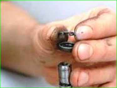
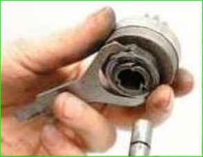
Remove the drive assembly with the lever.
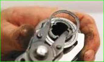
Remove the retaining ring from the lever
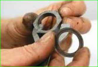
Remove the lever with the drive ring and washer
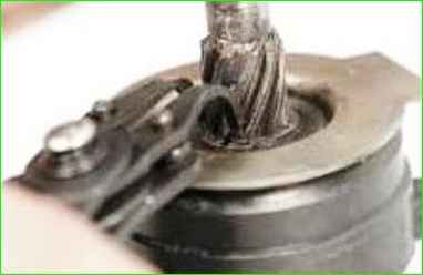
Remove the internal gear retaining ring.
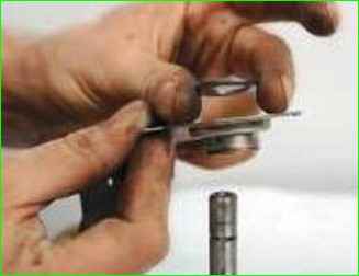
Remove the washer and shaft support.
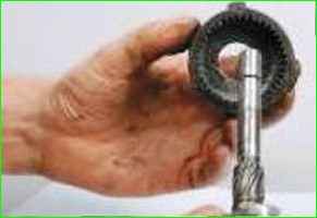
Remove the pinion with the internal engagement
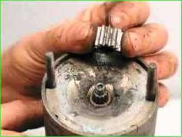
Remove the central gear from the anchor shaft
Inspect the gear.
If the gear teeth are heavily worn or broken, replace it.
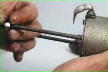
Remove the two tie rods.
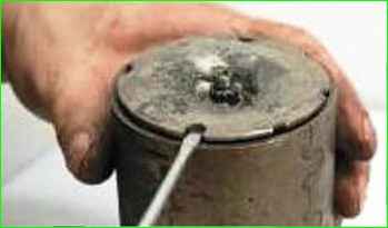
Pry off the anchor shaft support with a screwdriver.
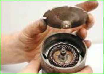
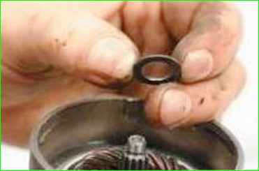
Note that a washer is installed on the armature shaft
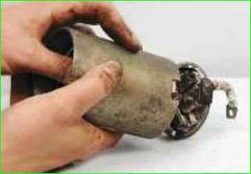
Remove the armature assembly with the brush holder from the stator housing
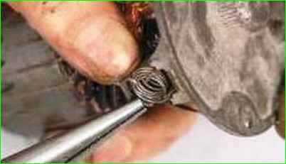
Bend back the brush spring clips and remove the springs.
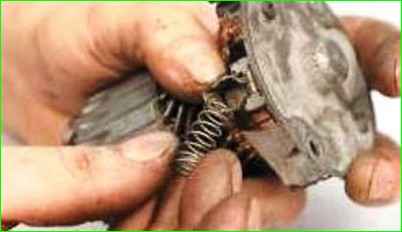
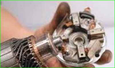
Remove the rear cover with the brush holder from the armature shaft.
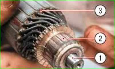
Inspect the armature.
If collector 1 is dirty or has scratches, traces of burning, etc, grind the commutator with fine glass sandpaper
If the commutator is significantly rough or if mica protrudes between its plates (lamellas), turn the commutator on a lathe and then grind it with fine glass sandpaper.
The runout of the core relative to the shaft journals should not exceed 0.08 mm.
Otherwise, replace the anchor.
If yellow deposits from the bearing are found on shaft 2 of the anchor, remove them with fine sandpaper.
If there are nicks or burrs on the surfaces of the journals and splines of the shaft, replace the anchor.
Check the reliability of the soldering of the terminals of winding 3 of the anchor to the commutator plates.
Inspect the winding at the ends of the anchor, the winding diameter should be less than the diameter of the package anchor iron. Otherwise, replace the anchor.
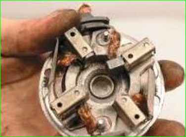
Inspect the brush holder.
Check the ease of movement of the brushes in the brush holder guides.
They should move without jamming, and the brush holder itself should not be damaged.
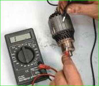
Check with a megohmmeter or a lamp powered by 220 V to see if there is a short circuit in the armature winding to ground.
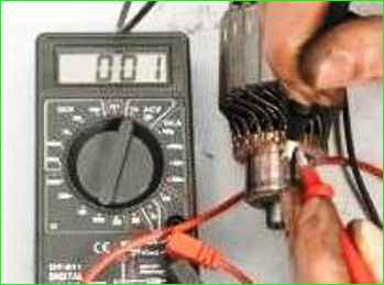
Check for short circuits between the armature winding sections or collector plates, are there any breaks in the place where the winding section terminals are soldered to the collector plates
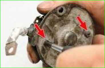
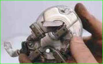
Turn out the two screws and remove the brush holder from the cover on the collector side
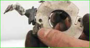
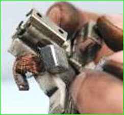
Remove the brush terminals and take out the brushes
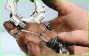
Remove the connecting bus
Inspect the connecting bus. Replace it if necessary.
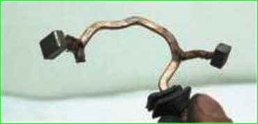
Assemble the starter in reverse order.
Before assembly, lubricate the drive gear teeth with engine oil, the drive shaft helical splines, the internal gear teeth, the planetary gears and the rotor shaft splines with consistent grease (TsIATIM-201, -202, -203 or Litol-24).


