Usually the steering column is removed to repair the steering column or electric power steering
Install the front wheels straight
Disconnect the negative terminal of the battery
Removing the steering column switches
Disconnect the wire blocks from the ignition switch, if necessary, remove the ignition switch
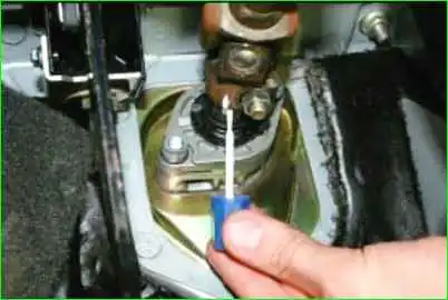
Mark the position of the propeller shaft on the drive gear
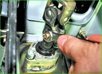
Using a 13 mm wrench or socket, unscrew the nut of the bolt securing the intermediate shaft to the steering gear shaft
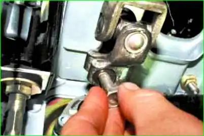
Remove the bolt

Use a flat-head screwdriver to open the terminal connection of the universal joint of the intermediate shaft
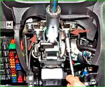
Using a 13mm socket, unscrew the two rear mounting nuts
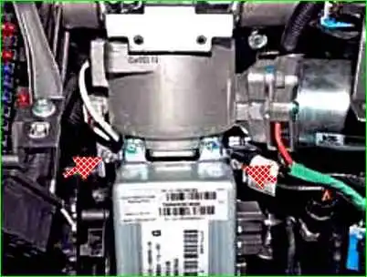
Unscrew the two nuts of the front steering column fastening
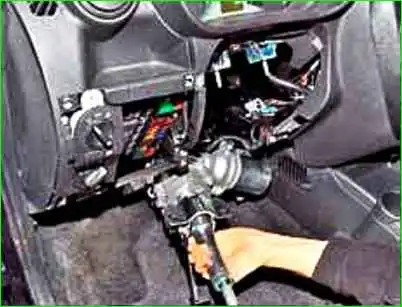
And lower the steering column to the floor
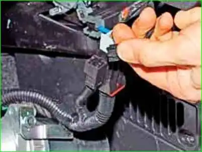
Pressing the block lock, disconnect the black wiring harness block from the electric power steering block
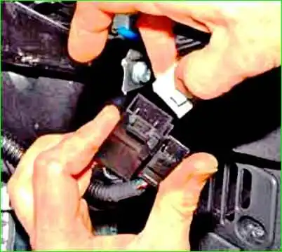
Also disconnect the gray wire block
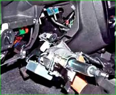
Remove the steering column with the intermediate shaft from under the instrument panel
The electric power steering control unit can be removed without removing the steering column.
Shown on the removed steering column
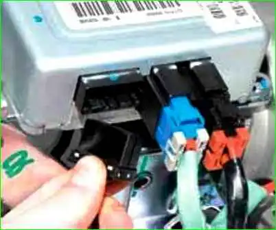
Pressing the block latches, disconnect the three wire blocks from the control unit connector
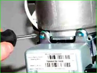
Use a Phillips screwdriver to unscrew the two screws
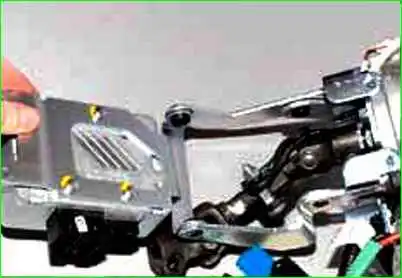
Rotate the bracket with the control unit
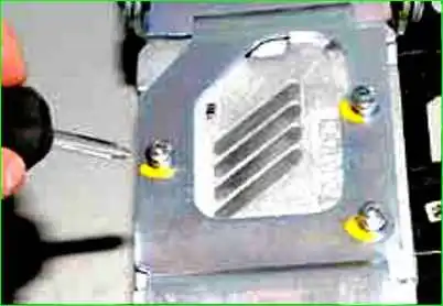
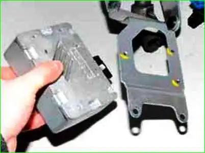
Use a Phillips screwdriver to unscrew the three screws and remove the control unit
To remove the intermediate driveshaft, turn the bracket n with a control unit.
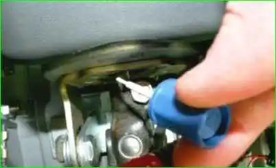
We use a marker to mark the relative position of the upper joint of the propeller shaft relative to the steering shaft
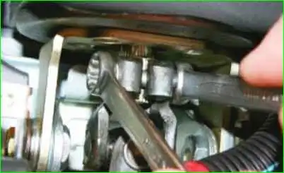
Using a 13mm spanner, unscrew the nut of the hinge coupling bolt
If the bolt turns, then hold it with a key at 13
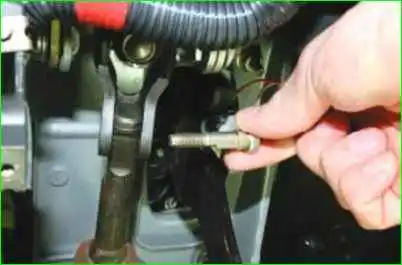
Remove the hinge bolt
Use a screwdriver to open the terminal connection of the hinge
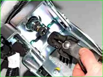
Remove the intermediate shaft
When connecting the upper hinge of the intermediate propeller shaft to the steering shaft, it is necessary to align the marks
Install the steering column in the reverse order.
Tighten the nuts of the coupling bolts on the flanges of the intermediate shaft to a torque of 23-28 Nm (23-2.8 kgf m).
Tighten the steering column mounting nuts to a torque of 15-18.6 Nm (1.5-1.9 kgf m).


