The engine management system turns the fuel pump on and off, controls the amount of air entering the engine cylinders, injects the required amount of fuel into the intake manifold, controls spark generation on the spark plugs, adjusts the ignition timing, regulates the crankshaft speed at idle, controls electric fan of the engine cooling system.
Engine control system - electronic, with distributed fuel injection.
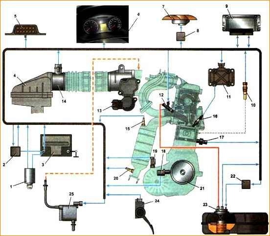
The system consists of the following elements:
- - electronic control unit;
sensors:
- 1) gas pedal position sensor;
- 2) throttle position sensor (built into the throttle assembly);
- 3) knock sensor;
- 4) coolant temperature sensor;
- 5) mass air flow sensor;
- 6) vehicle speed sensor;
- 7) two oxygen concentration sensors;
- 8) pressure sensor (for vehicles with air conditioning system)
Actuators:
- 1) main relay;
- 2) fuel pump relay;
- 3) nozzles;
- 4) ignition coils;
- 5) electric throttle drive;
- 6) cooling system electric fan relay;
- 7) instrument panel;
- 8) adsorber purge valve;
- - connecting wires;
- - diagnostic connector block.
An anti-theft system (immobilizer) is also integrated into the engine management system.
The main control element of the system is the electronic control unit (ECU), or, as it is often called, a controller with a built-in microprocessor.
Essentially, an ECU is a specialized mini-computer in which only one program is installed - engine control, and sensors and actuators form the peripheral equipment of this computer.
The unit receives and analyzes sensor signals.
Based on the received data, the block calculates control commands and issues them to actuators.
There are three types of memory in the unit: read-only memory (ROM), random access memory (RAM), and programmable memory (PROM).

ROM is non-volatile memory (that is, information in memory is retained when the power is turned off) and is a microcircuit “chip”.
The ROM stores the calculation program and the data necessary for the calculation (engine parameters, transmission ratios and other characteristics).
This information is individual for each car modification.
During operation, the ECU monitors the serviceability of all elements and circuits of the engine control system.
Having detected a malfunction, the ECU switches the engine management system to standby mode and turns on the control engine fault indicator light on the instrument panel.
The engine will be able to continue operating (except in the case of a malfunction of the crankshaft position sensor), which allows you to get to the repair site under your own power.
The ECU records detected fault codes in RAM. Operational information is also stored there, which the ECU microprocessor uses in calculations.
When the battery is disconnected from the vehicle's on-board network, all information stored in RAM will be deleted.
PROM stores codes for the vehicle's anti-theft system (immobilizer). This type of memory is non-volatile.
After activating the immobilizer, the ECU blocks the operation of the engine management system when trying to start the engine without special electronic keys
The engine control ECU is located behind the soundproofing cover, under the right side of the instrument panel.
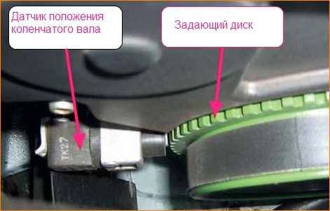
The crankshaft position sensor (CPS) is designed to generate signals by which the ECU synchronizes its operation with the engine operating cycles.
Therefore, this sensor is often called a synchronization sensor.
The operation of the sensor is based on the principle of induction - when the crankshaft pulley teeth pass the sensor core, AC voltage pulses appear in the sensor circuit.
The frequency of pulses corresponds to the crankshaft rotation speed.
The teeth are located around the circumference of the pulley (every 6˚).
Two of them are spaced from each other at an angular distance of 18°.
This was done to form reference signals in the sensor circuit - unique reference points relative to which the ECU determines the position of the crankshaft - top dead centers in the first-fourth and second-third cylinders.
Engine operation with a faulty crankshaft position sensor is impossible.
The crankshaft position sensor cannot be repaired; in the event of a malfunction, it is replaced as an assembly.
The knock sensor (DS) is piezoelectric and reacts to engine vibration.
Using sensor signals, the ECU determines the moment when detonation occurs during engine operation and, in accordance with this, adjusts the ignition timing.
In the event of a motor failure, the electronic control unit switches the system to backup mode.
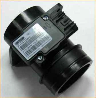
The mass air flow sensor (MAF) is installed between the air filter and the throttle valve.
Cars are equipped with a frequency-type mass air flow sensor, which has proven itself to be more reliable; with such a sensor, the output signal measures not voltage, but frequency.
Based on the sensor signal, the ECU calculates the amount of air entering the engine cylinders.
If the mass air flow sensor malfunctions, the electronic control unit switches the system to backup mode.
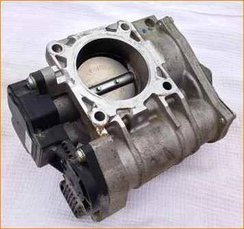
Throttle assembly
In order for engines to meet more stringent environmental standards, the throttle valve drive is equipped with a gear motor.
The gas pedal is electronic; it has no mechanical connection with the throttle valve.
Engine control is completely electronic.
The amount of air entering the engine cylinders is regulated by the throttle assembly, which is installed between the intake manifold receiver and the air filter.
The throttle valve is turned by an electric motor through a gearbox. Both are built into the throttle body.
When starting and warming up the engine, as well as in idling mode, the flow of air into the cylinders is regulated by opening the throttle valve.
The throttle position is controlled by two sensors built into the throttle body.
The throttle valve opening angle is set by the electronic control unit (ECU) depending on the estimated amount of air that should enter the engine cylinders.
This takes into account the engine operating mode (starting, warming up, idling, etc.), ambient temperature and engine, gas pedal position.
Control commands are sent to the throttle assembly to the electric motor.
At the same time, the ECU monitors the opening angle of the damper and, if necessary, sends appropriate commands to adjust its position.
As a result of the fact that the ECU simultaneously regulates the amount of injected fuel and incoming air, the optimal composition of the combustible mixture is maintained in any engine operating mode.
The electric throttle body is sensitive to deposits that may accumulate on its internal surface.
The resulting layer of deposits can interfere with the smooth movement of the throttle valve, jamming it (especially at low opening angles).
As a result, the engine will operate unstably and even stall at idle, start poorly, and failures may appear during transient conditions.
To avoid this, as a preventive measure, deposits should be removed with special detergent compounds during regular vehicle maintenance.
A large layer of deposits can completely block the movement of the damper. If flushing fails to restore the throttle assembly's functionality, it must be replaced.
A malfunction or incorrect operation of the throttle assembly may be caused by a broken contact in its electrical circuit (oxidized terminals in the wiring harness connection block).
In this case, it will be possible to restore operation by treating the terminals with a special compound for cleaning and protecting electrical contacts.
Other causes of the malfunction are possible:
- - no supply voltage is supplied to the throttle assembly;
- - signals are not received from both throttle position sensors;
- - The computer cannot recognize signals from the throttle position sensors.
In these cases, the engine control system goes into emergency mode.
At the same time, the car retains the ability to independently move a short distance at a slow speed, which, in extreme cases, will allow it to be moved to a safe place (pull to the side of the road, leave an intersection, etc.).
The fact that the throttle assembly is operating in emergency mode may be indicated by a burning indicator lamp for a malfunction of the engine management system and an increased speed of the crankshaft at idle (about 1500 min -1, despite the fact that the engine is warmed up to operating temperature ).
The engine will not respond to pressing the gas pedal.
Each of the throttle position sensors is a potentiometer.
During operation, gradual wear of conductive paths and moving contacts occurs.
Over time, wear may reach such an extent that correct operation of the sensor becomes impossible.
The presence of two sensors increases the reliability of the entire unit.
If only one sensor fails, the warning lamp will light up, but the engine management system will switch to backup mode.
In this case, the engine will respond adequately to pressing the gas pedal, but with worse parameters.
Standby mode allows you to drive your car to the repair site under your own power.
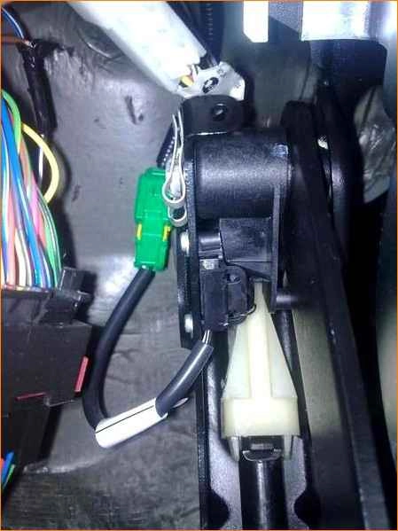
The electronic gas pedal consists of a plastic lever, which is integral with the pedal and two sensors built into the bracket.
All elements form a single structure, which is sometimes called the gas pedal module.
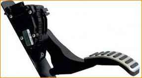
Each gas pedal position sensor (built into the gas pedal bracket) is a potentiometer, the moving contact of which is rigidly connected to the rotary axis of the pedal lever.
The electronic control unit (ECU) continuously monitors the position of the pedal using sensor signals.
The change in position is controlled by the changing resistance at the terminals of both sensors.
In accordance with these parameters, the ECU sends control commands to the throttle gear motor and fuel injectors.
As a result of wear of the moving contacts or conductive tracks, the sensors may fail or the signals coming from them will be incorrect.
If the signals are violated, the engine will operate unstably, and “failures” are possible in transient conditions.
When idling, the engine speed may change spontaneously.
If one of the sensors (or its circuit) fails, the engine control system fault warning lamp will light up.
If the signal from the sensor is not restored within the control time, the ECU will switch the system to backup mode.
In this mode, when you sharply press the gas pedal to stop, the speed will increase slowly.
The car will be able to continue driving to the repair site under its own power.
There may be a slight increase in fuel consumption and changes in some other technical parameters of the engine.
If both sensors fail, the ECU will switch the engine control system to emergency mode.
The engine will only run at speeds just above idle (1500 min -1).
At the same time, the car retains the ability to move independently, albeit at a slow speed.
This will allow you, if necessary, to leave the intersection, pull over to the side of the road, or move the car to a safe place a short distance.
In the engine control system, switching to some operating modes requires monitoring the position of the brake pedal.
The brake pedal switch is used as a brake pedal position sensor, which has two pairs of contacts.
The switch is connected to the ECU with an additional wire.
You will also need a sensor that monitors the engagement and disengagement of the clutch. It is installed in the clutch pedal bracket.
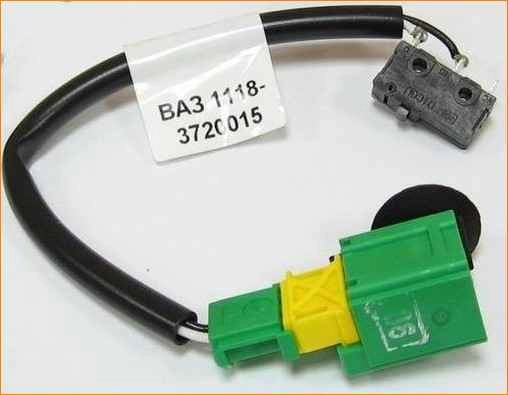
The clutch pedal position sensor works on the same principle as the brake light switch.
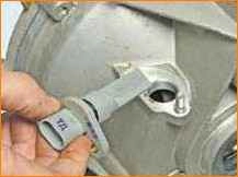
The oxygen concentration sensor provides an output signal from which the ECU determines the oxygen concentration in the exhaust gases.
Based on the received data, the ECU adjusts the amount of fuel injected into the engine cylinders, thereby maintaining the optimal proportion of the air-fuel mixture (this is necessary for the efficient operation of the catalytic converter).
The sensing element of the oxygen concentration sensor is located in the exhaust gas flow (before the catalytic converter).
The sensor can only operate if its sensitive element is heated to a temperature of at least 300˚ C.
To reduce warm-up time, a heating element is built into the sensor.
To ensure that the engine complies with EURO IV toxicity standards, a second oxygen concentration sensor is built into the exhaust system after the converter.
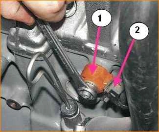
Coolant temperature sensor (CTS) is a semiconductor device thermistor, the electrical resistance of which changes with changes in ambient temperature.
DTOZH is installed in the thermostat housing.
By the resistance of the sensor, the ECU estimates the thermal conditions of the engine.
The data obtained is used to calculate most control commands for elements of the engine control system, as well as to turn on the electric fan of the engine cooling system.
If the DTOZH malfunctions, the electronic control unit switches the system to backup mode.
The vehicle speed sensor is installed on the gearbox.
The operating principle of the sensor is based on the Hall effect.
Using the pulses generated by the sensor, the ECU calculates the vehicle speed.
The signal from the sensor is also sent to the speedometer.
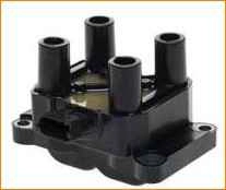
Ignition coil
The engine ignition system uses one ignition coil.
It consists of two two-terminal ignition coils, made in a single housing.
Sparking occurs in two cylinders simultaneously (1-4 or 2-3).
The ignition coil is connected to the spark plugs by four high-voltage wires with permanent tips.
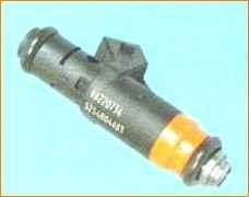
The nozzle is an electromagnetic needle valve, the outlet of which has a spray nozzle with four calibrated holes.
The injector opens based on a signal from the computer, and fuel under pressure is injected directly into the intake valve.
Quantity top The flow entering the cylinder is regulated by the opening time of the nozzle.
The engine has one injector for each cylinder.
The canister purge valve is installed on the air filter housing
The diagnostic connector block is designed to connect an external diagnostic device to the engine management system.
The block is installed to the right of the center console.
Basic data for monitoring, adjustment and maintenance
- Spark plug marking (manufacturer) - А17ДВРМ LR15YC-1 (BRISK) WR7DCX (BOSCH)
- Spark plug thread M14x1.25
- The gap between the electrodes is 1.0-1.15 mm
- Engine ignition coil 2111-3705010-10
- Engine injectors 1118-1132010/-01
- Canister purge valve 1118-1164200
- Crankshaft position sensor 2112-3847010-00/-04
- Coolant temperature sensor (TCS) 2112-3851010-00/-05
- Throttle assembly 2116-1148010
- Knock sensor 2112-3855020-01/-02/-03
- Mass air flow sensor 11180-1130010
- Oxygen concentration sensor 21074-3850010-20
- Vehicle speed sensor 1118-3843010-04
- Electronic gas pedal 11183-1108500
Tightening torques for threaded connections
Name of components and parts - Tightening torque Nm (kgf-m)
- Crankshaft position sensor mounting bolt 8.0-12.0 (0.8-1.2)
- Mass air flow sensor mounting bolts 3.0-5.0 (0.3-0.5)
- Knock sensor mounting bolt 10.4-24.2 (1.0-2.4)
- Coolant temperature sensor 9.3-15(0.9-1.5)
- Oxygen concentration sensor 25.0-45.0 (2.5-4.5)
- Spark plugs 30.7-39.0 (3.1-4.0)
- Screws for securing ignition coils 6.0-8.0 (0.6-0.8)
- Electronic gas pedal mounting nuts 8.0-12.0 (0.8-1.2)
")

")
")
")
")
")
")
")